Eureka AIR delivers breakthrough ideas for toughest innovation challenges, trusted by R&D personnel around the world.

Plug-in connector

a plug-in connector and connector technology, applied in the field of plug-in connectors, can solve the problems of affecting the overall installation size, the production process of the plug-in connector, and the disadvantage of the number of components, so as to achieve reliable plug-in connection, short size, and not require a lot of time and money

Active Publication Date: 2015-01-13
HUBERSUHNER AG
View PDF11 Cites 9 Cited by
  • Summary
  • Abstract
  • Description
  • Claims
  • Application Information

AI Technical Summary

Benefits of technology

[0008]It is the object of the present invention to create a simply designed plug-in connector which comprises few components, is short in size, produces a reliable plug-in connection, ensures sufficient protection of the conductor, does not require a lot of time and money to produce and has low production costs.
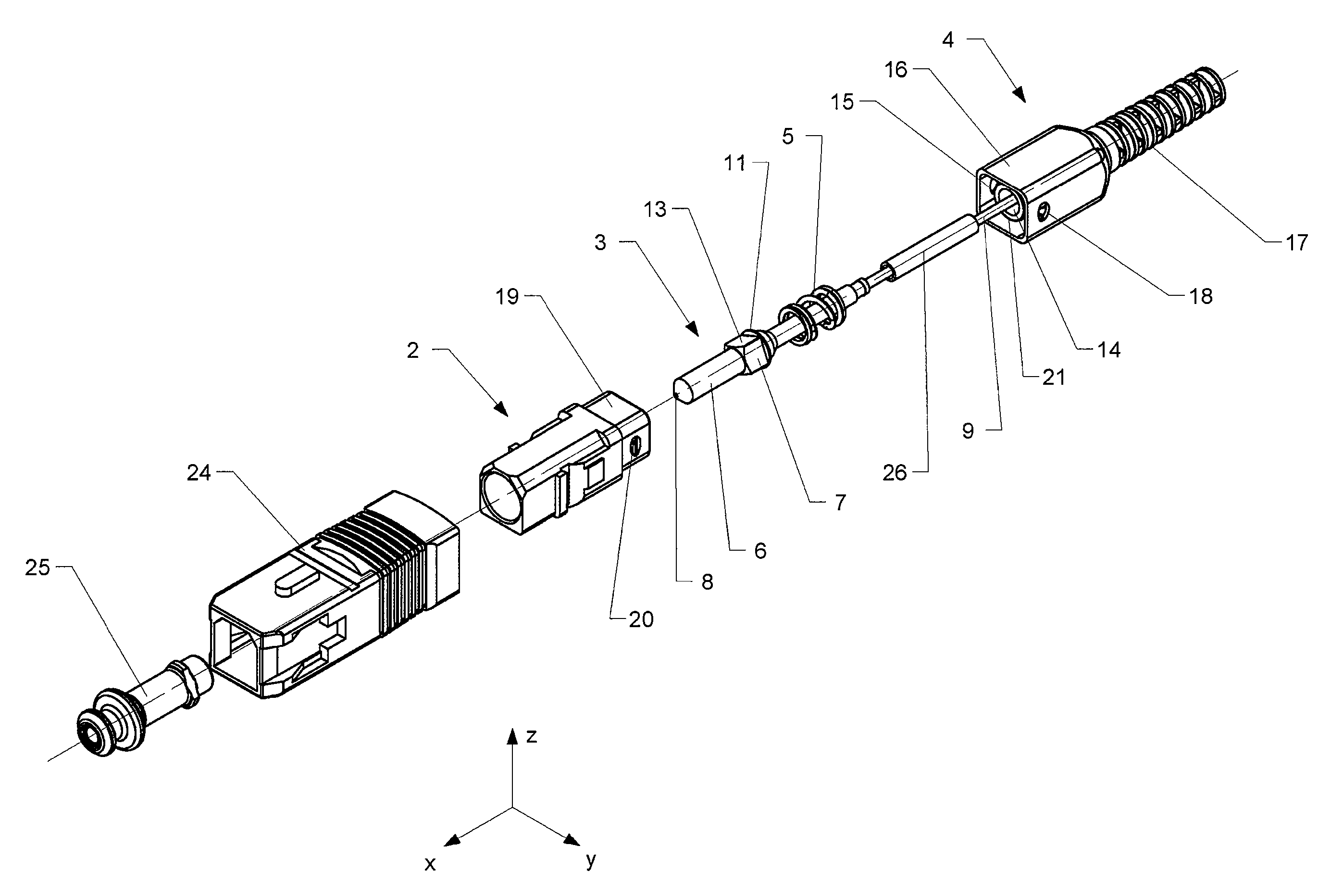
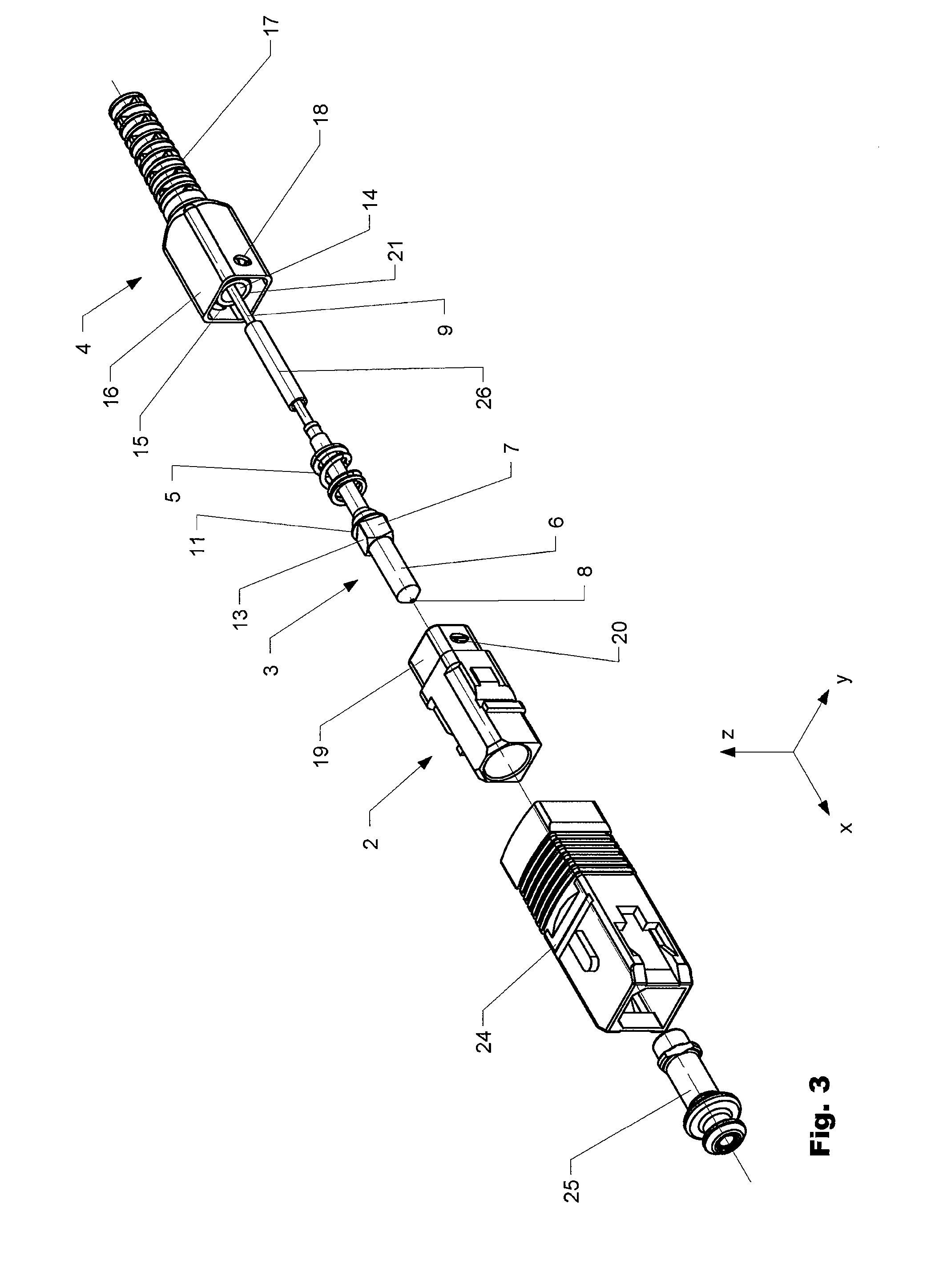
[0010]As claimed in the invention, the plug-in connector manages with only three basic components which are aligned with respect to one another and are positioned in relation to one another by means of the spring element. Essentially only two components are necessary for the secure guiding and bearing arrangement of the conductor holder as such. Consequently, compared to known plug-in connector systems, a smaller number of components are required for realizing a plug-in connector. Consequently, production costs are lower and production times are reduced. In addition, the risk of predetermined and necessary tolerance values being exceeded during production or when the components are fitted together or of the components being aligned in a non-precise manner with respect to one another is reduced. All in all, the plug-in connector as claimed n the invention is designed in a simple manner and is consequently less susceptible to faults during production and to faulty operation during the use of a plug-in connector.
[0021]By means of the number of components reduced compared to the prior art and the multi-functional use of the present components, the plug-in connector as claimed in the invention can be produced in a cost-effective and rapid manner. At the same time, a high level of precision can be achieved to meet the necessary standards.

Problems solved by technology

Even the smallest irregularities at a connection point can disturb or completely interrupt a transmission.
A large number of components have a disadvantageous effect on the overall installation size and the production process of the plug-in connector.

Method used


Image

  • Plug-in connector
  • Plug-in connector
  • Plug-in connector

Examples


Embodiment Construction

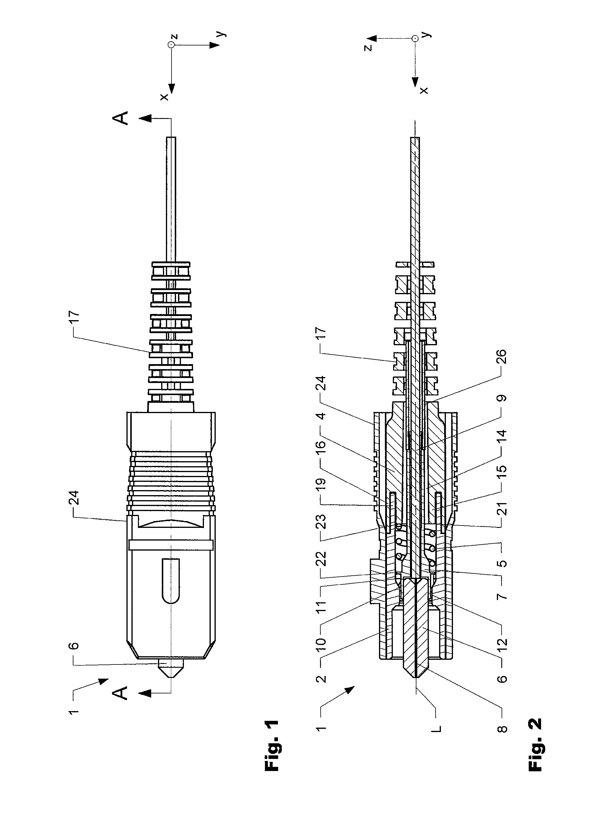
[0026]A plug-in end shown on the left-hand side in the figures, by way of which the plug-in connector can be inserted into a further connection piece (not shown), designates a front end of the plug-in connector. A cable end shown on the right-hand side, from which a conductor cable protrudes out of the plug-in connector, designates a rear end. A longitudinal axis L extends centrally through the plug-in connector.

[0027]FIG. 1 shows a view of a plug-in connector 1 as claimed in the invention in the manner of an SC connector. An unlocking body 24, which serves as a type of housing for a basic body 2, an anti-kink element 4 and a spring element 5, can be seen in the figure. At the front end a ferrule 6 projects out of the unlocking body 1 and the basic body. A bending region 17 of the anti-kink element exits at the rear end and surrounds a conductor cable.

[0028]The unlocking body 24 can cooperate by way of a locking device with a further plug-in connector, for example of a device of ano...


PUM


Abstract

The invention relates to a plug-in connector for connecting at least one conductor, in particular a conductor cable with an optical conductor, comprising a main body (2) having a continuous opening, a tube-like conductor holder (3) and an anti-kink element (4). The conductor holder (3) is arranged at least partially inside the main body and movably mounted therein. The anti-kink element (4) protrudes at least partially over the main body (2). A spring element (5) is provided for positioning the conductor relative to the main body (2) and is clamped between the conductor holder (3) and the anti-kink element (4).

Description

BACKGROUND OF THE INVENTION[0001]1. Field of the Invention[0002]The invention is in the field of plug-in connectors for the connection of at least one conductor, in particular in the field of plug-in connectors for conductor cabling with an optical conductor.[0003]2. Discussion of Related Art[0004]Plug-in connectors are known from the state of the art in order to be able to connect conductors, such as, for example, an optical conductor to a device or to another conductor or to be able to join them to the same. For this purpose, the plug-in connector can be releasably plugged into a further plug-in connector, or by means of a coupling, can be plugged-in on a device or another conductor with which the connection is to be made. In particular in the case of optical conductors, precise positioning of the conductor inside a plug-in connection is necessary in order to ensure a perfect optical transmission. Even the smallest irregularities at a connection point can disturb or completely int...

Claims


Application Information

Patent Timeline
Patent Type & Authority Patents(United States)
IPC IPC(8): G02B6/36G02B6/38
CPCG02B6/3851G02B6/3887G02B6/36G02B6/38875
Inventor SCOPIC, NESAZAINA, PATRICKGADMER, LAIF
Owner HUBERSUHNER AG
Why Eureka
Eureka Blog
Learn More