Methods and systems for transitioning between braking modes

a technology of braking mode and braking system, which is applied in the direction of braking components, machines/engines, motor/generator/converter stoppers, etc., can solve the problems of not always being able to operate with regenerative braking, and the conversion of the vehicle's kinetic energy into heat, so as to reduce the driveline braking torque, increase the friction braking torque, and reduce the effect of driving line braking torqu

Active Publication Date: 2015-01-13
FORD GLOBAL TECH LLC
View PDF20 Cites 37 Cited by
  • Summary
  • Abstract
  • Description
  • Claims
  • Application Information

AI Technical Summary

Benefits of technology

[0004]The inventors herein have recognized the above-mentioned disadvantages and have developed a method for vehicle braking, comprising: providing driveline braking torque to a vehicle without applying friction braking torque to the vehicle; and reducing driveline braking torque while increasing friction braking torque to the vehicle in response to an energy storage device state of charge, the friction braking torque increased by a same amount the driveline braking torque is reduced.
[0005]By increasing friction brake torque by a same amount regenerative braking is reduced, it may be possible to transition between braking modes without disturbing the driver. For example, if regenerative braking is reducing braking torque by 2 N-m per second, friction braking may be increased by 2 N-m per second so that the friction brake torque provides the braking torque that is being reduced by the driveline. Consequently, the friction brakes counteract the decrease in driveline braking. In this way, it may be possible to transition between braking modes without disturbing a driver.
[0006]The present description may provide several advantages. Specifically, the approach may reduce braking disturbances. Further, the approach may improve vehicle drivability.

Problems solved by technology

On the other hand, friction braking converts the vehicle's kinetic energy into heat which is dissipated and lost to the surrounding atmosphere.
Nevertheless, it is not always possible to operate with regenerative braking since a vehicle has limited electrical storage capacity.

Method used


Image

  • Methods and systems for transitioning between braking modes
  • Methods and systems for transitioning between braking modes
  • Methods and systems for transitioning between braking modes

Examples


Embodiment Construction

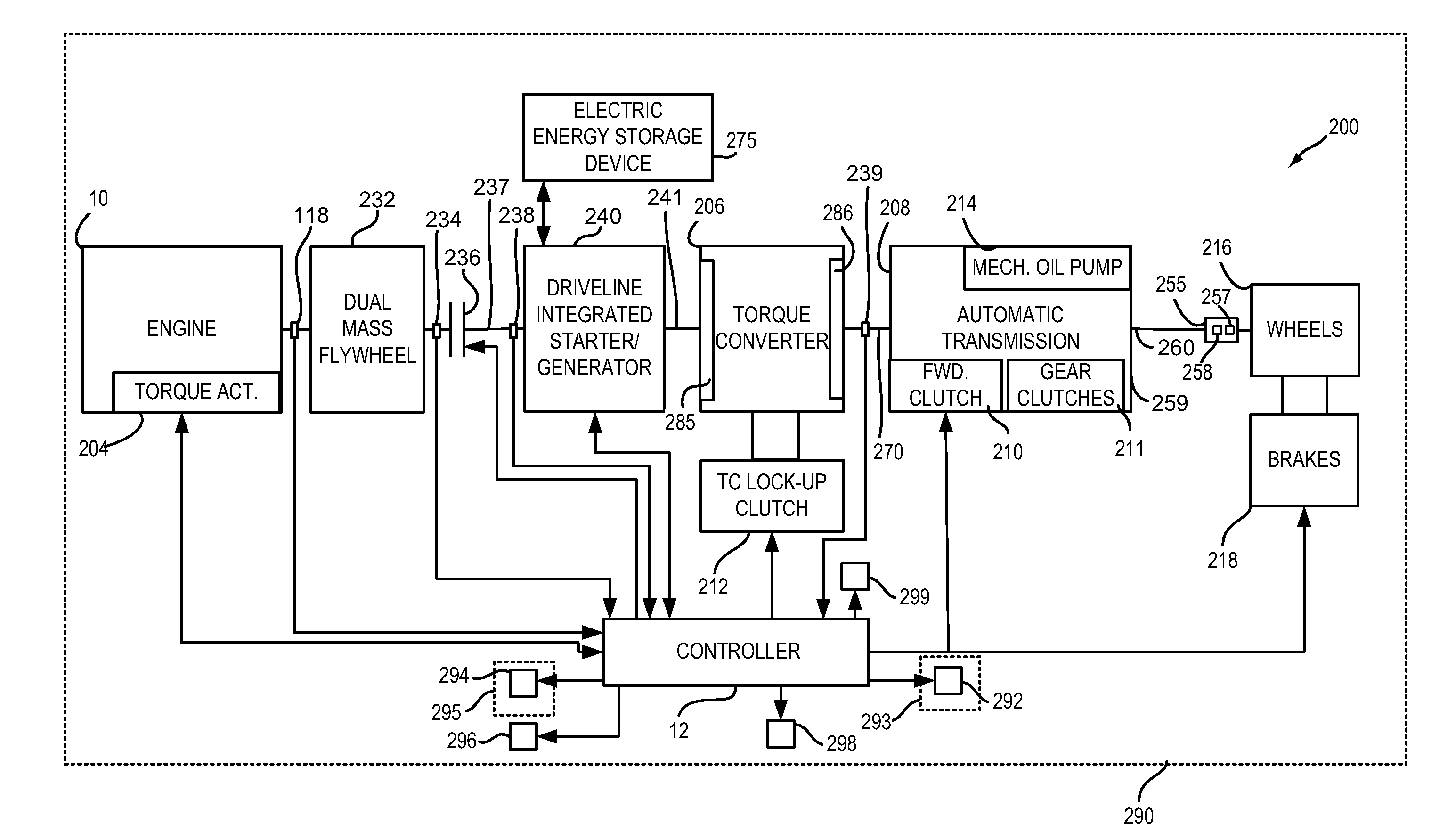
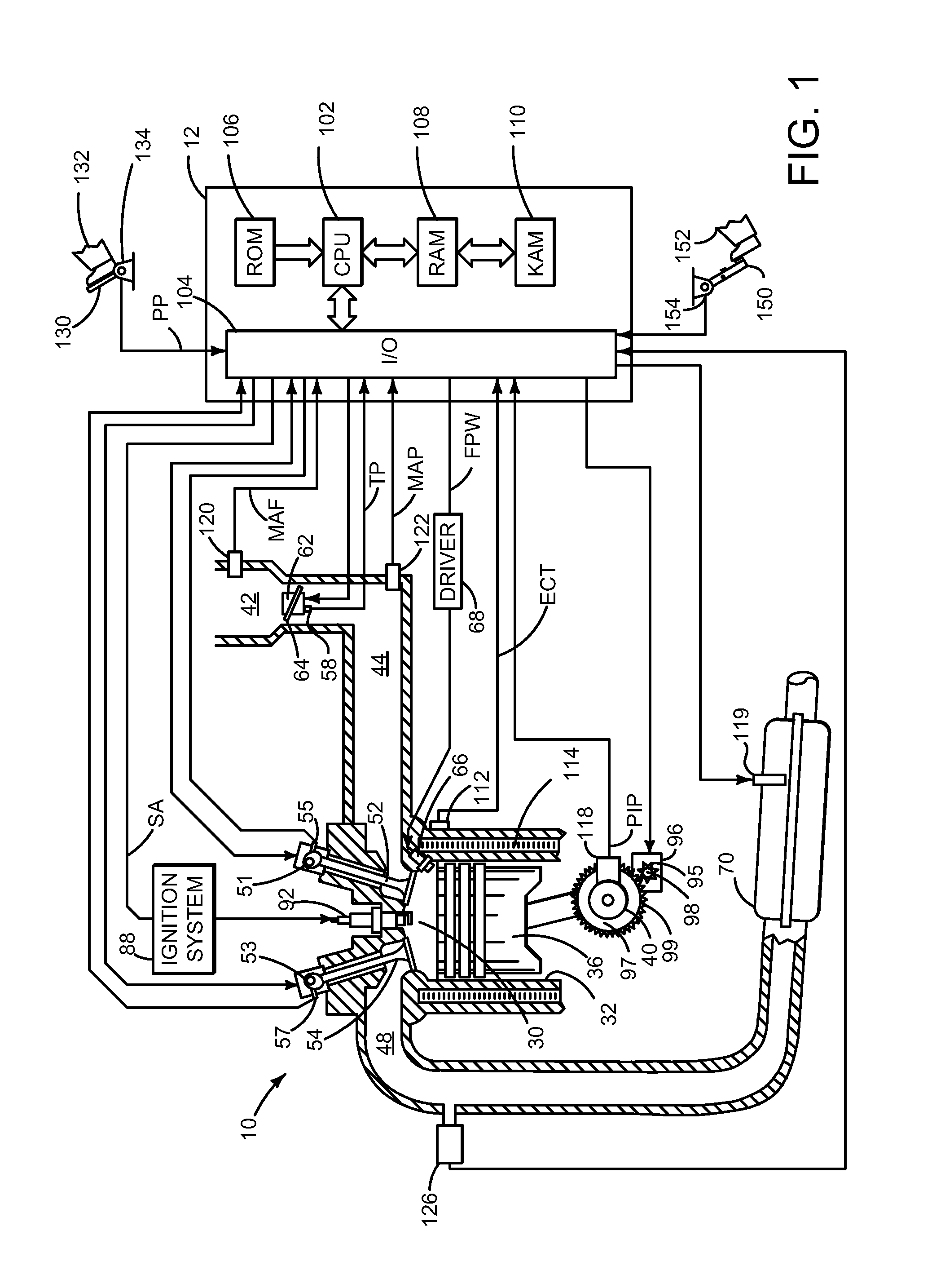
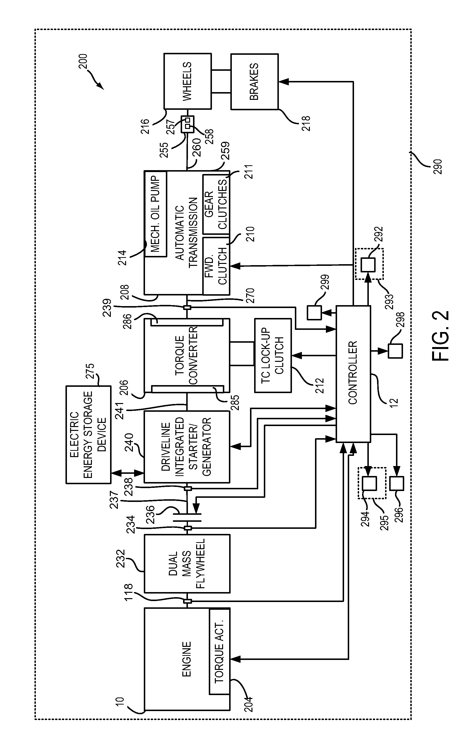
[0026]The present description is related to controlling a driveline of a hybrid vehicle. The hybrid vehicle may include an engine and electric machine as shown in FIGS. 1-3. The engine may be operated with or without a driveline integrated starter / generator (e.g., an electric machine or motor that may be abbreviated DISG) during vehicle operation. The driveline integrated starter / generator is integrated into the driveline on the same axis as the engine crankshaft and rotates whenever the torque converter impeller rotates. Further, the DISG may not be selectively engaged or disengaged with the driveline. Rather, the DISG is an integral part of the driveline. Further still, the DISG may be operated with or without operating the engine. The mass and inertia of the DISG remain with the driveline when the DISG is not operating to provide or absorb torque from the driveline.

[0027]The driveline may be operated according to the method of FIG. 4. In some examples, the driveline may be operat...


PUM


Abstract

Systems and methods for improving operation of a hybrid vehicle are presented. In one example, a method for transitioning between driveline braking and wheel brakes is provided.

Description

CROSS REFERENCE TO RELATED APPLICATIONS[0001]The present application claims priority to U.S. of America Provisional Patent Application 61 / 643,147 filed on May 4, 2012, the entire contents of which are hereby incorporated by reference for all purposes.FIELD[0002]The present description relates to a system and methods for improving drivability and fuel economy of a vehicle. The methods may be particularly useful for engines that are selectively coupled to an electrical machine and a transmission.BACKGROUND AND SUMMARY[0003]Hybrid vehicles may include regenerative braking and friction braking to stop a vehicle. During regenerative braking, the vehicle's kinetic energy is converted into electrical energy and stored for later use. On the other hand, friction braking converts the vehicle's kinetic energy into heat which is dissipated and lost to the surrounding atmosphere. Thus, it may be beneficial to operate with regenerative braking when braking is requested. Nevertheless, it is not al...

Claims


Application Information

Patent Timeline
Patent Type & Authority Patents(United States)
IPC IPC(8): B60W10/02B60W10/08B60W10/06B60W10/184B60W10/196B60L1/02B60L7/26B60L11/18B60L50/16B60L50/30B60W10/04B60W20/00B60W30/18
CPCB60W10/184B60W10/04B60W10/196B60W10/08B60W20/00B60W30/18109B60W30/18127B60L1/02B60L7/26B60L11/14B60L11/16B60L11/1816B60L11/1861B60W2710/182B60W2510/084B60L2200/36B60L2230/22B60L2240/12B60L2240/34B60L2240/421B60L2240/423B60L2240/441B60L2240/443B60L2240/445B60L2240/486B60L2240/507B60L2260/52B60L2260/54B60L2270/145B60T2270/604Y02T10/7077Y02T10/7088Y02T10/7044Y02T10/7005Y02T10/705Y02T10/7033Y02T10/642Y02T90/121Y02T90/14Y02T10/7027Y02T10/70Y10T477/89Y10T477/38Y10T477/24Y10T477/814B60L50/16B60L50/30B60L58/12B60L53/51Y10S903/93B60W20/14Y02T10/64Y02T10/7072Y02T90/12B60L7/18B60W10/06B60W10/11B60W10/188B60W30/18118
Inventor BANKER, ADAM NATHANGIBSON, ALEX O'CONNORDOERING, JEFFREY ALLENMCCALLUM, JAMES WILLIAM LOCHOSHINSKY, DAVID
Owner FORD GLOBAL TECH LLC
Why Eureka
Try Eureka