Combination pressure/temperature in a compact sensor assembly
What is AI technical title?
AI technical title is built by Patsnap AI team. It summarizes the technical point description of the patent document.
a sensor assembly and compact technology, applied in the field of compact sensor assembly of conjugated pressure/temperature, can solve the problems of large size, difficult manufacturing, and high manufacturing cost of conventional devices, and achieve the effect of reducing the size of the pressure/temperature sensor assembly and being highly robus
Active Publication Date: 2015-01-20
SENSATA TECHNOLOGIES INC
View PDF5 Cites 10 Cited by
Summary
Abstract
Description
Claims
Application Information
AI Technical Summary
This helps you quickly interpret patents by identifying the three key elements:
Problems solved by technology
Method used
Benefits of technology
Benefits of technology
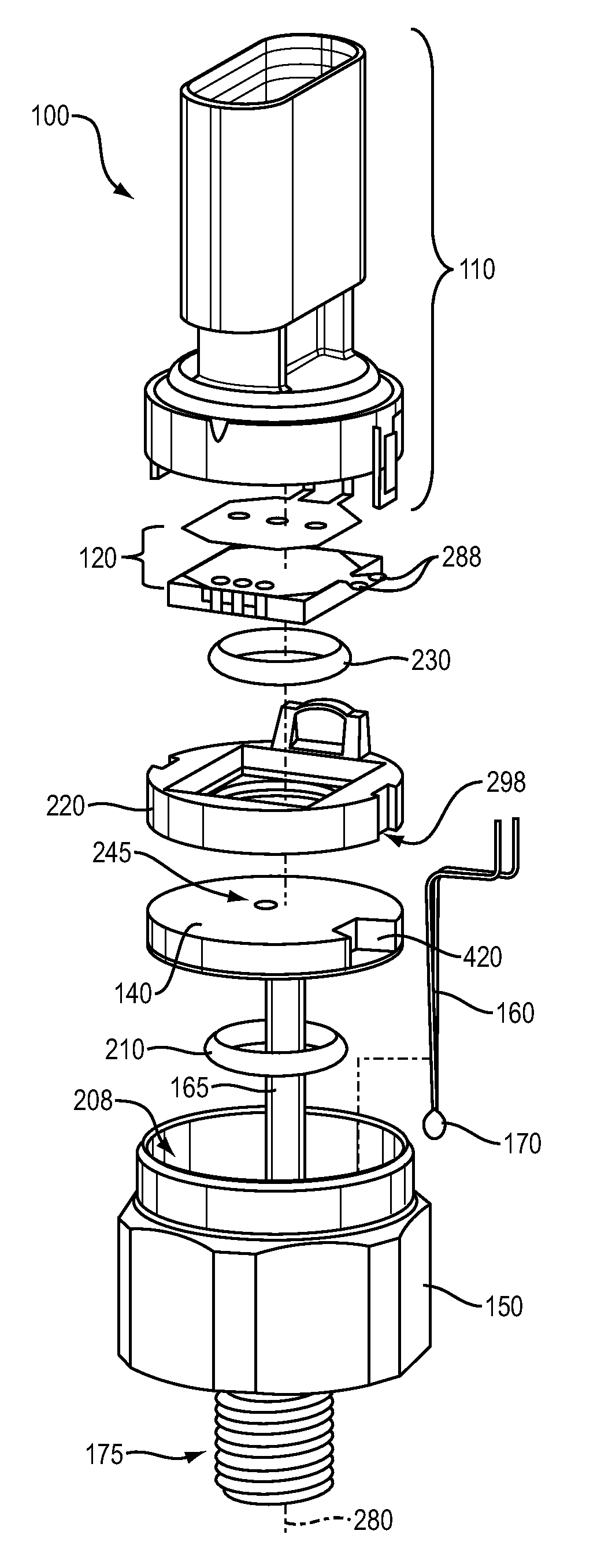
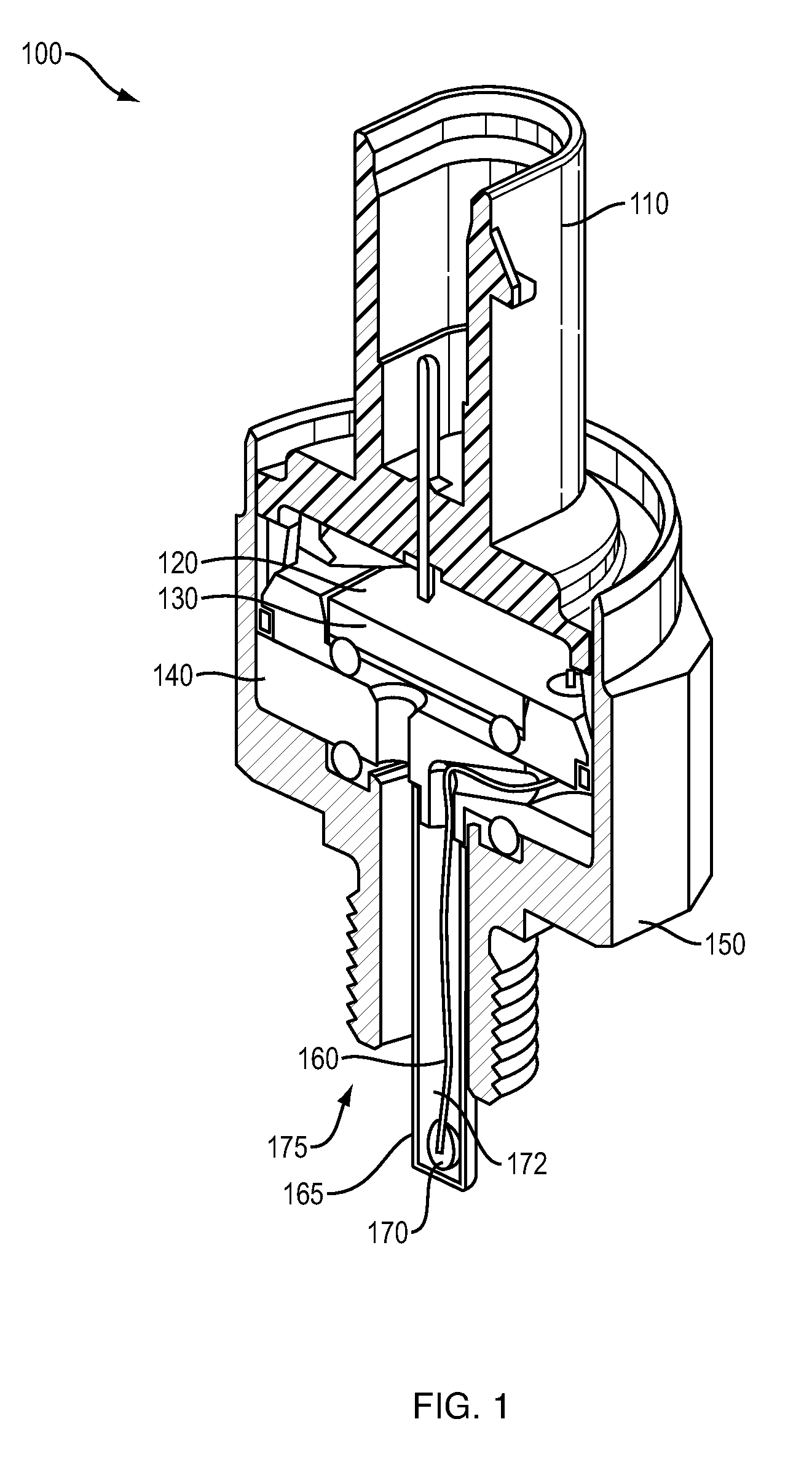
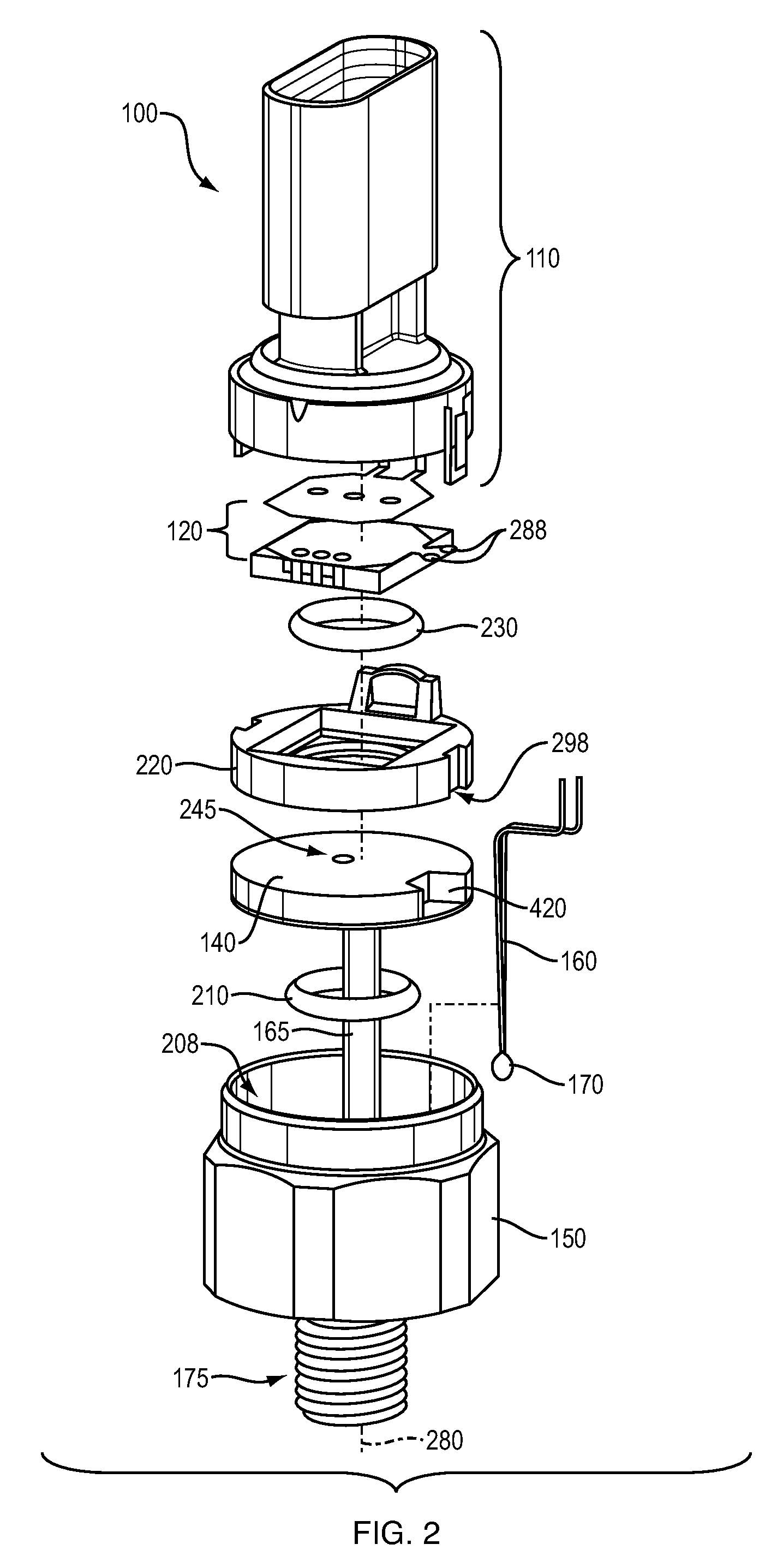
[0013]More specifically, in one embodiment, a sensor assembly includes a rectangular-shaped pressure sensor element (i.e. ceramic pressure sensor element) and an electronic circuitry coupled to receive a signal from the rectangular-shaped pressure sensor element. The pressure sensor element senses a pressure of a fluid. The sensor assembly can include an open-ended fluid-tight passageway in which to convey the fluid from a portal opening of the sensor assembly to a surface of the rectangular-shaped pressure sensor element that senses the pressure. The sensor can further include a closed-ended fluid-tight passageway, at least a portion of which is fabricated from a material such as metal. In contrast to the open-ended fluid tight passageway, the closed-ended fluid tight passageway prevents physical exposure to the fluid being monitored. The closed-ended fluid tight passageway extends from at least from the portal opening of the sensor assembly to the electronic circuitry on at least a portion of a path adjacent to the rectangular-shaped pressure sensor element. The sensor assembly can further include a temperature sensor element disposed in an end of the closed-ended fluid-tight passageway nearer the portal opening. At least one conductive link disposed in the closed-ended fluid tight passageway can electrically couple the temperature sensor element to the electronic circuitry.
[0014]In accordance with further embodiments, to provide better thermal response, the sensor assembly can include thermally conductive filling disposed in at least a portion of the closed-ended fluid-tight passageway. The thermally conductive filling provides a thermally conductive path between the temperature sensor element and the end of the closed-ended fluid-tight passageway in which the temperature sensor element resides. The end of the closed-ended fluid tight passageway can include a hollowed metal probe or tube in which the temperature sensor element resides. Because it is closed and fluid-tight, the hollowed metal probe prevents exposure of the temperature sensor element inside of the tube to the fluid. The hollowed metal probe can be made of any suitable material such as stainless steel, brass, etc. depending on the type of fluid that is being measured.
[0015]In contrast to use of injection molds as discussed above in conventional applications, the hollowed metal probe according to embodiments herein also can be made of any suitable length without the need to create a costly injection mold.
Problems solved by technology
However, such conventional devices are typically expensive to manufacture, are large in size, and are subject to damage.
Circular pressure sensor elements are expensive and difficult to manufacture.
Forming a hole in the circular pressure sensor element can be costly as it requires rather precise hole location.
A drawback of such a design is that the plastic coating on the temperature sensor element does not provide a high degree of protection against damage.
For example, when the sensor assembly including the plastic coated temperature sensor element is dropped from a height of one meter, the plastic coated temperature sensor element can easily crack.
If the sensor assembly is then used in an intended application to monitor pressure / temperature of a caustic fluid, the temperature sensor element would be exposed to the fluid causing damage.
This may increase its strength; however, the sensor assembly becomes very large in size.
Use of an injection molding processor to create a coating to protect the temperature sensor element is undesirable because any adjustments to the length will require a new injection mold.
This is undesirable as injection molds are expensive.
Method used
Image
Click on the blue label to locate the original text in one second.
Reading with bidirectional positioning of images and text.
Examples
Embodiment Construction
[0047]As discussed above, embodiments herein deviate with respect to conventional sensor assemblies. For example, in contrast to conventional systems, certain embodiments herein are directed to reducing a size of a pressure / temperature sensor assembly, while providing a highly robust sensor assembly that can survive a drop test without being damaged.
[0048]More specifically, FIG. 1 is an example cutaway perspective view of a sensor assembly including pressure sensor element and temperature sensor element according to embodiments herein.
[0049]As shown, sensor assembly 100 includes a rectangular-shaped pressure sensor element 130 (to sense a pressure of a fluid) and electronic circuitry 120 coupled to receive a signal from the pressure sensor element 130.
[0050]Although embodiments herein discuss use of a rectangular-shaped pressure sensor element, other suitable types of pressure sensor elements can be used in sensor assembly. The use of the rectangular-shaped pressure sensor element a...
PUM
Property
Measurement
Unit
size
aaaaa
aaaaa
size
aaaaa
aaaaa
height
aaaaa
aaaaa
Abstract
A sensor assembly includes a rectangular-shaped pressure sensor element and an electronic circuitry coupled to receive a signal from the pressure sensor element. An open-ended fluid-tight passageway of the sensor assembly conveys fluid from a portal opening of the sensor assembly to a surface of the rectangular-shaped pressure sensor element. The sensor assembly further includes a closed-ended fluid-tight passageway, at least a portion of which is fabricated from metal. The closed-ended fluid tight passageway extends from at least from the portal opening of the sensor assembly to the electronic circuitry on at least a portion of a path adjacent to the rectangular-shaped ceramic pressure sensor element. The sensor assembly includes a temperature sensor element disposed in an end of the closed-ended fluid-tight passageway. Conductive links disposed in the closed-ended fluid tight passageway electrically couple the temperature sensor element to the electronic circuitry.
Description
CROSS REFERENCE TO RELATED APPLICATIONS[0001]The present application claims the benefit of U.S. Provisional Patent Application No. 61 / 524,989, filed on Aug. 18, 2011, which is incorporated herein by reference.BACKGROUND[0002]Conventional sensor devices have been used to measure environmental conditions. For example, via signal information generated by a conventional pressure sensor device, it is possible to monitor and electrically convey pressure conditions to a remote location over a wired link. An example of a pressure sensor assembly is shown in U.S. Pat. No. 4,875,135 granted to Bishop. In certain cases, conventional sensor devices include both a temperature sensor and a pressure sensor to measure both a temperature and a pressure of a respective environment. Examples of combination pressure / temperature sensor assemblies are shown in U.S. Pat. No. 5,974,893, U.S. Pat. No. 7,000,478, U.S. Pat. No. 7,762,140, U.S. Pat. No. 4,716,492, U.S. Pat. No. 7,434,470 and U.S. Patent Public...
Claims
Application Information
Patent Timeline
Application Date:The date an application was filed.
Publication Date:The date a patent or application was officially published.
First Publication Date:The earliest publication date of a patent with the same application number.
Issue Date:Publication date of the patent grant document.
PCT Entry Date:The Entry date of PCT National Phase.
Estimated Expiry Date:The statutory expiry date of a patent right according to the Patent Law, and it is the longest term of protection that the patent right can achieve without the termination of the patent right due to other reasons(Term extension factor has been taken into account ).
Invalid Date:Actual expiry date is based on effective date or publication date of legal transaction data of invalid patent.
InventorPAPADEAS, NICHOLAS G.SILVERIA, JEFFREY PETERGHANI, OMAR RASHIDGIRROIR, JARED E.ZWIJZE, ALBERT FERDINANDGENNISSEN, PAULUS THOMAS JOHANNESNORBERG, EDWARD

