Steering system

a steering system and steering column technology, applied in the direction of steering column, steering parts, vehicle components, etc., can solve the problems of large sliding resistance between the outer tube and the inner tube, inability to smoothly slide between the two tubes relative to each other, and inability to reduce the sliding resistance. , to achieve the effect of reducing the sliding resistance and reducing the siz

Inactive Publication Date: 2015-01-20
JTEKT CORP
View PDF18 Cites 10 Cited by
  • Summary
  • Abstract
  • Description
  • Claims
  • Application Information

AI Technical Summary

Benefits of technology

[0010]A steering system according to an aspect of the invention includes an outer tube at an upper side and an inner tube at a lower side that support a steering shaft so that the steering shaft is rotatable, the outer tube and the inner tube sliding relative to each other in an axial direction when shock is absorbed, and the steering shaft having one end to which a steering member is coupled; a first sliding resistance reducing element that is retained in at least a circumferential lower region of an axial upper end portion of the inner tube, comes into contact with an inner periphery of the outer tube, and reduces sliding resistance between the outer tube and the inner tube; and a second sliding resistance reducing element that is retained in at least a circumferential upper region of an axial lower end portion of the outer tube, comes into contact with an outer periphery of the inner tube, and reduces the sliding resistance between the outer tube and the inner tube.
[0011]In the steering system according to the above-described aspect, the first sliding resistance reducing element, which comes into contact with the inner periphery of the outer tube at the upper side, is retained in at least the circumferential lower region of the axial upper end portion of the inner tube at the lower side, and the second sliding resistance reducing element, which comes into contact with the outer periphery of the inner tube, is retained in at least the circumferential upper region of the axial lower end portion of the outer tube. Accordingly, even when a moment that tilts the outer tube with respect to the inner tube is generated so as to push up the axial upper end portion of the outer tube at the upper side at the time of a secondary collision of a vehicle, the outer tube and the inner tube can be caused to slide relative to each other smoothly due to the function of the first sliding resistance reducing element and the function of the second sliding resistance reducing element. Since the length of fit between the outer tube and the inner tube can be made as short as possible, size reduction can be achieved while securing a predetermined shock-absorbing stroke.

Problems solved by technology

However, since the steering wheel tends to be pushed upward at the time of the secondary collision, a twist is apt to be caused between the outer tube and the inner tube.
If the twist is caused, the sliding resistance between both the tubes may become large and both the tubes may not be able to smoothly slide relative to each other when shock is absorbed.
In the case where the length of fit between both the tubes is set to be long in order to reduce the twist between both the tubes when shock is absorbed, it is difficult to reduce the size of the steering system in the axial direction while securing a required shock-absorbing stroke.

Method used


Image

  • Steering system
  • Steering system
  • Steering system

Examples


Embodiment Construction

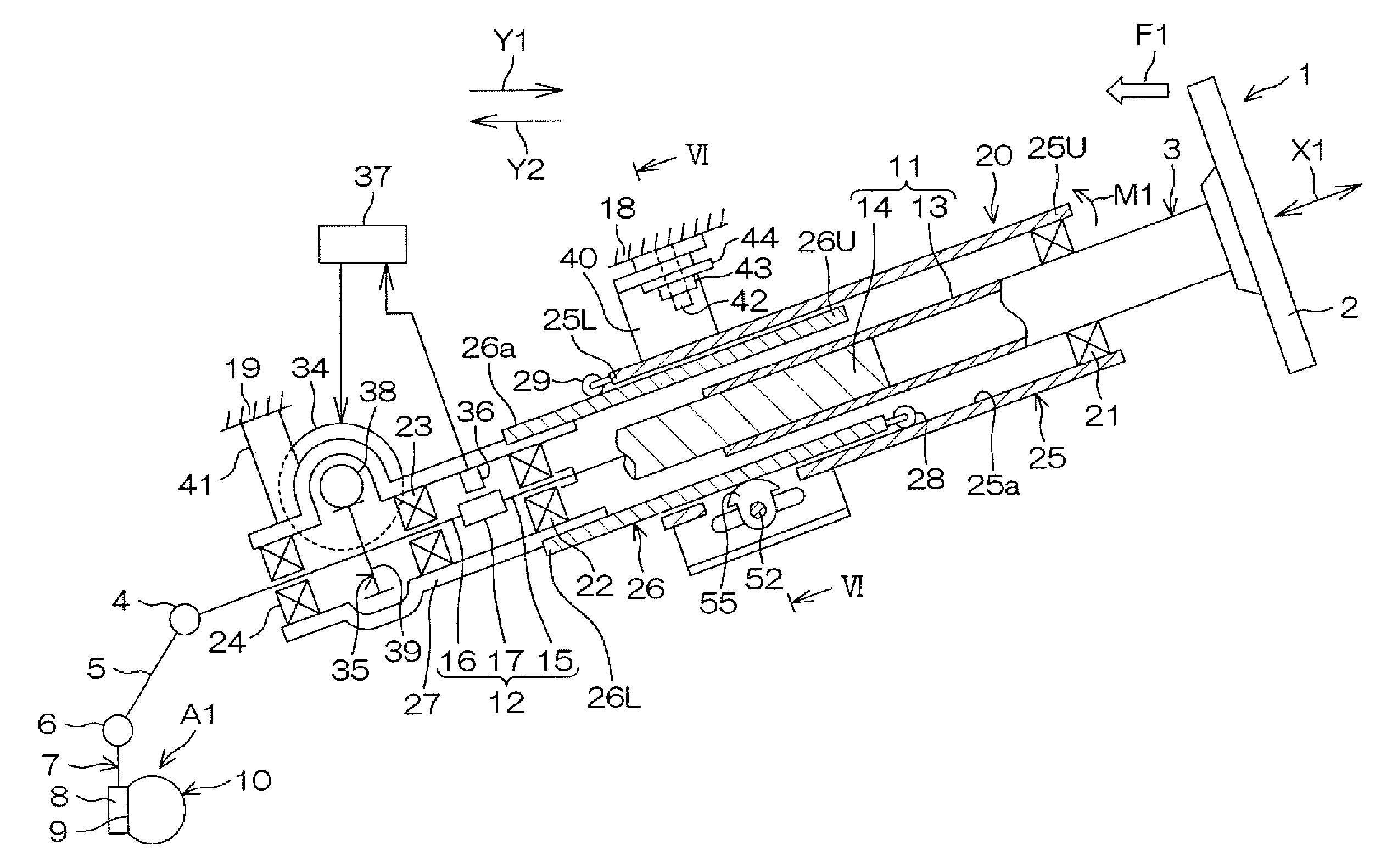
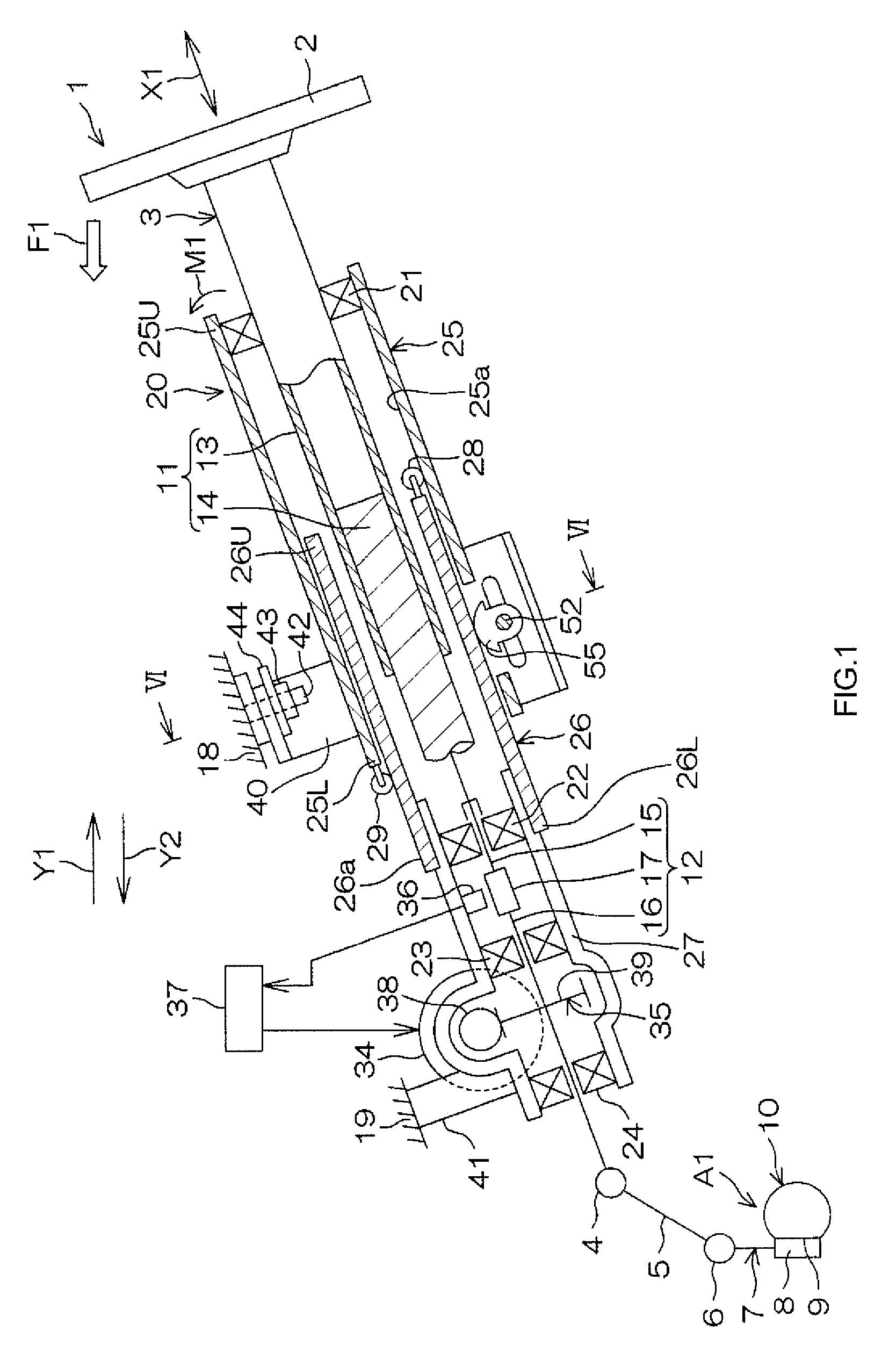
[0034]Hereinafter, embodiments of the invention will be described with reference to the accompanying drawings. FIG. 1 is a schematic view of the schematic configuration of a steering system of an embodiment of the invention. Although the present embodiment will be described according to a case where the steering system is an electric power steering system, the invention may be applied to a manual steering system. Referring to FIG. 1, a steering system 1 includes a steering shaft 3 that is coupled to a steering member 2, such as a steering wheel, an intermediate shaft 5 that is coupled to the steering shaft 3 via a universal joint 4, a pinion shaft 7 that is coupled to the intermediate shaft 5 via a universal joint 6, and a rack shaft 8 as a steered shaft, which has a rack 8a that meshes with a pinion 7a provided in the vicinity of an end portion of the pinion shaft 7.

[0035]A steered mechanism A1 is constituted by a rack-and-pinion mechanism including the pinion shaft 7 and the rack ...


PUM


Abstract

A steering system includes an outer tube at an upper side and an inner tube at a lower side that slide relative to each other in an axial direction when shock is absorbed. A first sliding resistance reducing element, which comes into contact with an inner periphery of the outer tube, and reduces sliding resistance between both the tubes, is retained in at least a circumferential lower region of an axial upper end portion of the inner tube. A second sliding resistance reducing element, which comes into contact with an outer periphery of the inner tube, and reduces the sliding resistance between both the tubes, is retained in at least a circumferential upper region of an axial lower end portion of the outer tube.

Description

INCORPORATION BY REFERENCE[0001]The disclosure of Japanese Patent Application No. 2012-255417 filed on Nov. 21, 2012 including the specification, drawings and abstract, is incorporated herein by reference in its entirety.BACKGROUND OF THE INVENTION[0002]1. Field of the Invention[0003]The present invention relates to a steering system.[0004]2. Description of the Related Art[0005]In a telescopic adjustment type steering system that adjusts the position of a steering wheel, which is a steering member, in an axial direction of a steering shaft, an inner shaft and an outer shaft that constitute the steering shaft are fitted to each other so as to be non-rotatable relative to each other and slidable relative to each other in the axial direction, and both the shafts are caused to slide relative to each other in the axial direction so as to perform telescopic adjustment. For example in Japanese Patent Application Publication No. 2006-151011 (JP 2006-151011 A), in a steering shaft, a rolling...

Claims


Application Information

Patent Timeline
Patent Type & Authority Patents(United States)
IPC IPC(8): B62D1/19B62D1/185
CPCB62D1/185B62D1/192
Inventor SUGIURA, TOMONORI
Owner JTEKT CORP
Why Eureka
Try Eureka