
Electromagnetic linear valve

a technology of linear valves and working fluids, applied in valve details, valve arrangements, braking systems, etc., can solve the problems of unsuitably controlling the pressure difference between the high the low-pressure-side working fluid pressure, and causing self-vibration upon opening and closing of the valve, so as to reduce increase the amount of parts, and reduce friction.

Inactive Publication Date: 2015-01-27
TOYOTA JIDOSHA KK
View PDF15 Cites 6 Cited by
  • Summary
  • Abstract
  • Description
  • Claims
  • Application Information

AI Technical Summary

Benefits of technology

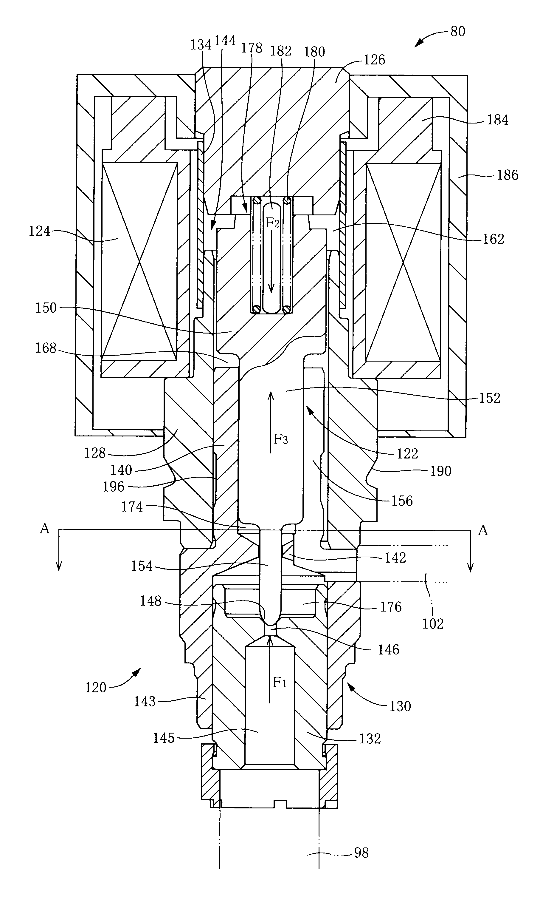
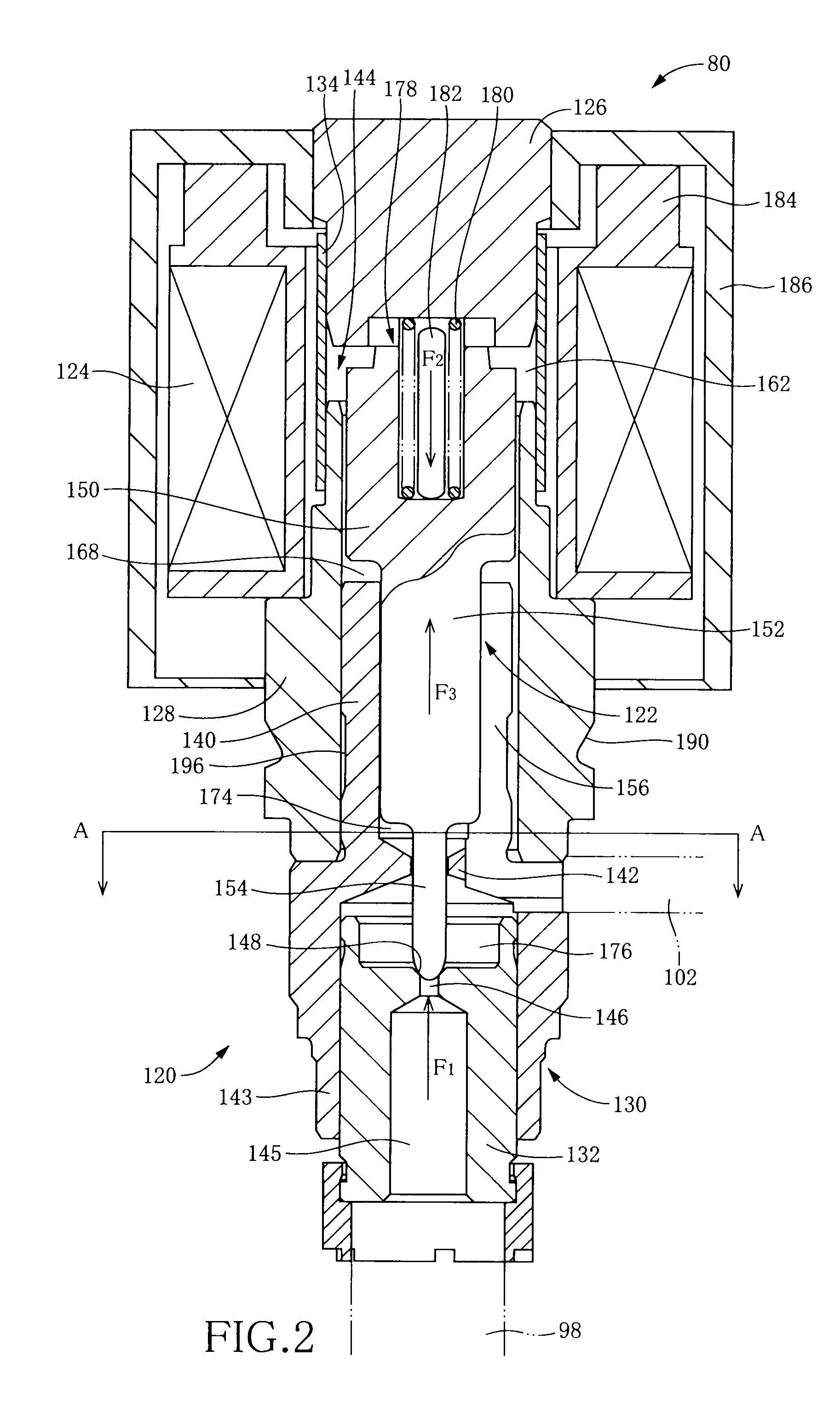
[0010]In each of the electromagnetic linear valves according to the present invention, as described above, the amount of the part of the magnetic flux flowing to the contact portions of the plunger and the inner circumferential surface of the housing, is smaller than the amount of the entire magnetic flux flowing within the plunger. Thus, it is possible to increase the amount of the magnetic flux flowing within the plunger and to reduce the amount of the part of the magnetic flux flowing to the contact portions of the plunger and the inner circumferential surface of the housing. Therefore, in each of the electromagnetic linear valves according to the invention, the electromotive force based on the electromagnetic induction whose amount is enlarged to a certain degree, can be generated, while the friction force generated between the plunger and the inner circumferential surface of the housing can be reduced. That is, the self-vibration of the plunger can be restrained without a large friction force being generated between the plunger and the inner circumferential surface of the housing.(B) Modes of the Invention
[0104]Further, in the electromagnetic linear valve described in this mode (23), when the magnetic flux flows between the plunger and the housing upon formation of the magnetic field, magnetic saturation takes place in the second flux-passing portion of the plunger since the second flux-passing portion of the plunger allows flow of the magnetic flux by a smaller amount therein than the first flux-passing portion of the plunger. In this instance, the magnetic flux flowing within the plunger is divided into a part flowing within the first flux-passing portion and a part flowing within the second flux-passing portion. Further, during movement of the plunger, the second flux-passing portion and the inner circumferential surface of the housing are in contact with each other, without the first flux-passing portion and the inner circumferential surface of the housing being in contact with each other. Therefore, an amount of the part of the magnetic flux flowing to contact portions at which the plunger and the inner circumferential surface of the housing are in contact with each other, is smaller than an amount of the magnetic flux flowing within the plunger. That is, even if a certain amount of the magnetic flux flows within the plunger, it is possible to reduce the amount of the part of the magnetic flux flowing to the contact portions of the plunger and the inner circumferential surface of the housing. Therefore, in the electromagnetic linear valve according to this mode (23), as well as in the electromagnetic linear valve according to this mode (1), it is possible to generate the electromotive force whose amount is enlarged to a certain degree and to reduce the friction force generated between the plunger and the inner circumferential surface of the housing. That is, the self-vibration of the plunger can be restrained without a large friction force being generated between the plunger and the inner circumferential surface of the housing.

Problems solved by technology

In the electromagnetic linear valve constructed as described above, there is a risk that self-vibration could be caused upon opening and closing of the valve, since the plunger is supported by the elastic body in the housing.
Therefore, if the friction force between the plunger and the housing is increased, there is a risk that the pressure difference between the high-pressure-side working fluid pressure and the low-pressure-side working fluid pressure could not be suitably controlled.

Method used


Image

  • Electromagnetic linear valve
  • Electromagnetic linear valve
  • Electromagnetic linear valve

Examples


Embodiment Construction

[0011]There will be described various modes of the invention (hereinafter referred to as “claimable invention” where appropriate) deemed to contain claimable features for which protection is sought. Each of these modes of the invention is numbered like the appended claims and depends from the other mode or modes, where appropriate, for easier understanding of the technical features disclosed in the present specification. It is to be understood that the claimable invention is not limited to the technical features or any combinations thereof which will be described in each of these modes. That is, the scope of the claimable invention should be interpreted in the light of the following descriptions accompanying the various modes and preferred embodiment of the invention. In a limit in accordance with such an interpretation, a mode of the claimable invention can be constituted by not only any one of these modes but also either a mode provided by any one of these modes and additional com...


PUM


Abstract

An electromagnetic linear valve includes: (a) a plunger including a large outside-diameter portion and a small outside-diameter portion, and (b) a housing having a through-hole and including a large inside-diameter portion in which the large outside-diameter portion is inserted with a clearance being defined between the large inside-diameter portion and the large outside-diameter portion, and a small inside-diameter portion in which the small outside-diameter portion is inserted with a clearance being defined between the small inside-diameter portion and the outside-diameter portion. The plunger has an end portion which serves as a valve body that is to be seated on a valve seat constituted by an opening of the through-hole. The large outside-diameter portion has an end portion constituted by another end portion of the plunger that is opposite to the above-described end portion of the plunger. The clearance between the small inside-diameter portion and the small outside-diameter portion is smaller than the clearance between the large inside-diameter portion and the large outside-diameter portion.

Description

TECHNICAL FIELD[0001]The present invention relates to an electromagnetic linear valve which has a housing and a plunger disposed movably in its axial direction in the housing, and which is to be opened and closed by movement of the plunger.BACKGROUND ART[0002]An electromagnetic linear valve has a plunger and a housing. The plunger includes an end portion serving as a valve body that is to be seated on a valve seat provided in the housing. In a state in which the valve body is seated on the valve seat, flow of a working fluid in a direction away from a working fluid passage of a high-pressure side toward a working fluid passage of a low-pressure side is inhibited. In a state in which the valve body is separated from the valve seat, the flow of the working fluid in the direction away from the working fluid passage of the high-pressure side toward the working fluid passage of the low-pressure side is allowed. The electromagnetic linear valve further has an elastic body and a coil. The ...

Claims


Application Information

Patent Timeline
Patent Type & Authority Patents(United States)
IPC IPC(8): F16K31/06B60T8/36B60T8/40F16K1/34
CPCF16K31/0648B60T8/367B60T8/4081F16K1/34F16K31/0658
Inventor NANAHARA, MASAKISATO, KEI
Owner TOYOTA JIDOSHA KK
Learn More