
Hydraulic tensioner

a technology of hydraulic tensioner and tensioner body, which is applied in the direction of mechanical equipment, belts/chains/gearings, and screws. it can solve the problems of inability to eliminate the generation of flapping noise, inability to regulate the bleeding of air from difficulty in setting the gap when inserting screws. it can improve the deaeration rate of the high-pressure oil chamber, prevent flapping noise, and quickly and smoothly bleed air

Active Publication Date: 2015-01-27
TSUBAKIMOTO CHAIN CO
View PDF7 Cites 3 Cited by
  • Summary
  • Abstract
  • Description
  • Claims
  • Application Information

AI Technical Summary

Benefits of technology

This patent aims to solve issues in hydraulic tensioners by providing a mechanism to quickly and smoothly bleed air from the high-pressure oil chamber, preventing the oil damping force from dropping and controlling tension in a chain without generating flapping noises. The invention solves these problems through a deaeration regulating screw, deaeration guide groove, and axial force exerted by a deaeration regulating washer. Additionally, the patent describes improvements in the design of the threaded hole and concave curved surface to further enhance the deaeration process.

Problems solved by technology

The prior art chain tensioner described above is unable to bleed air from high-pressure oil chamber reliably through the microscopic helical thread clearance, and is therefore unable to eliminate the generation of flapping noises.
However, it is difficult to set the gap when inserting the screw.
Therefore the tensioner is unable to regulate the bleeding of air from the high-pressure oil chamber.
In addition, because of the presence of the gap, the spring may not exert sufficient force to lock the screw adequately.

Method used


Image

  • Hydraulic tensioner
  • Hydraulic tensioner
  • Hydraulic tensioner

Examples


Embodiment Construction

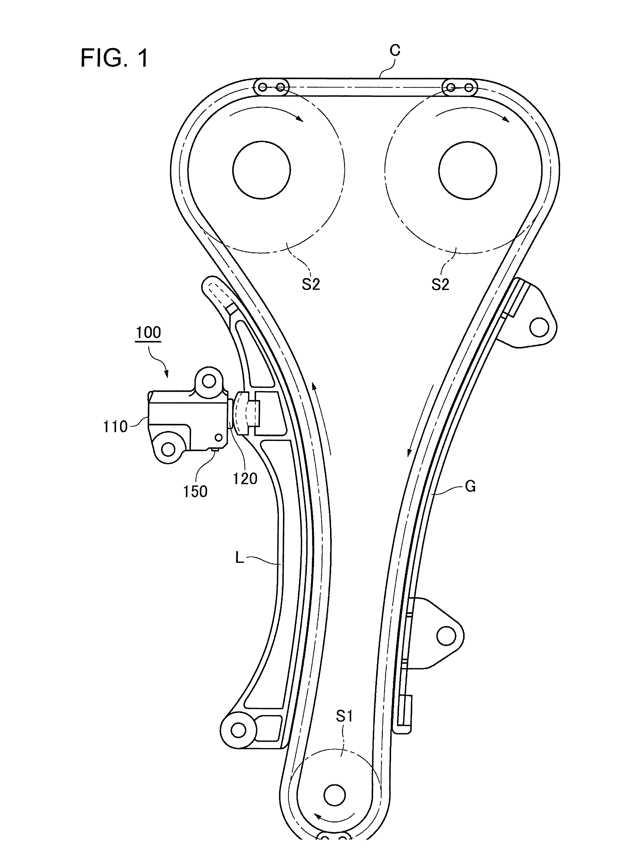
[0025]FIG. 1 shows the timing drive of a dual overhead cam (DOHC) internal combustion engine in which an endless timing chain C is driven by a crankshaft sprocket S1 and drives a pair of camshaft sprockets S2. Arrows show the directions of sprocket rotation and chain travel. A hydraulic tensioner 100 is located adjacent the slack side of a timing chain C, i.e., the span of the chain that travels from the crankshaft sprocket 51 toward one of camshaft sprockets S2. A plunger 120 protrudes from the housing 110 of the tensioner to apply tension to the slack side of the timing chain through a pivoted lever L. The tensioner housing and lever L can be mounted on the engine block (not shown). A stationary guide G guides a travel of the tension side of the timing chain, i.e., the span that travels from a camshaft sprocket S2 toward the crankshaft sprocket S1.

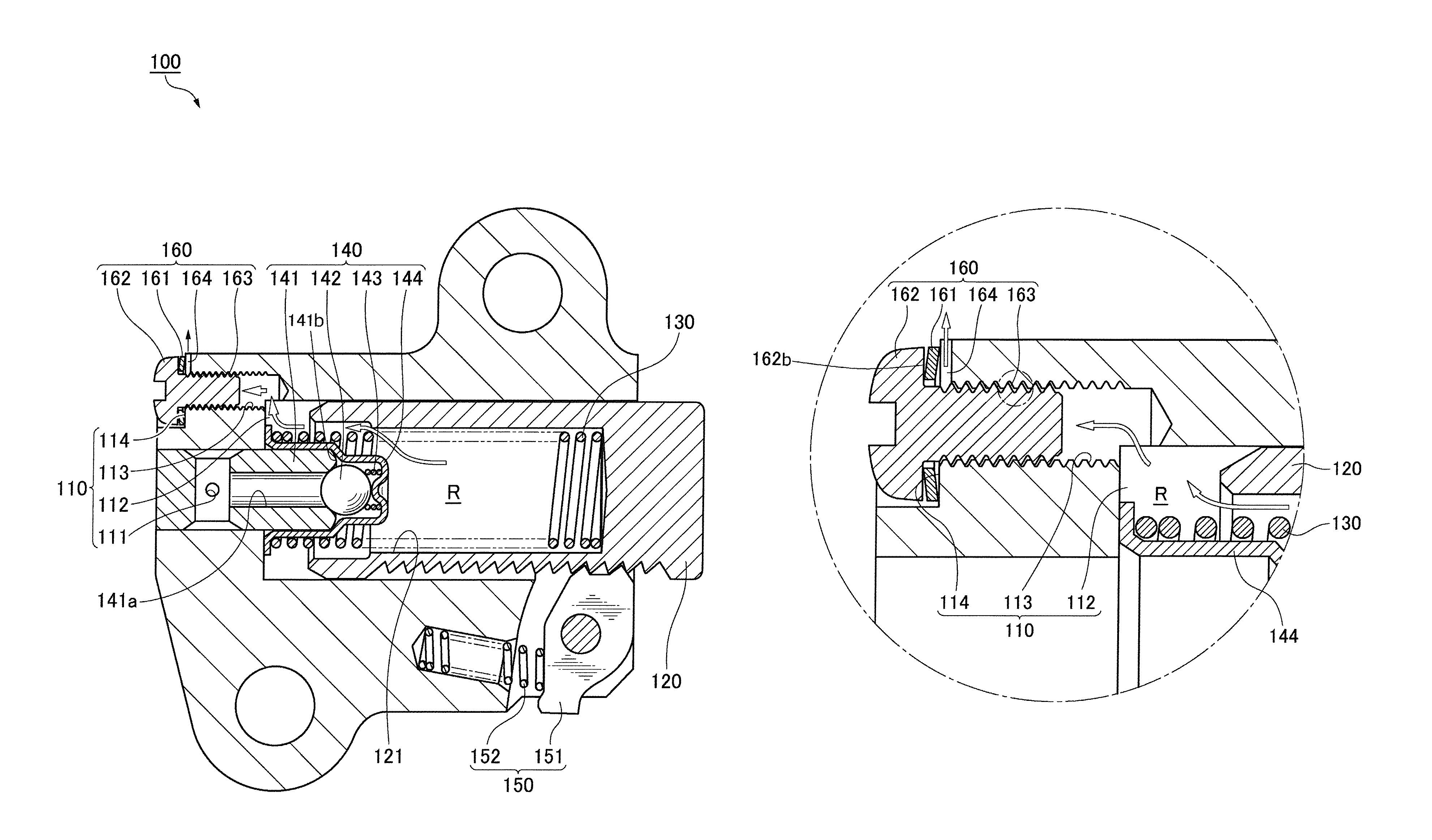
[0026]As shown in FIG. 3, an oil supply passage 111 formed in the housing 110 for introduction of oil supplied under pressure from the ...


PUM


Abstract

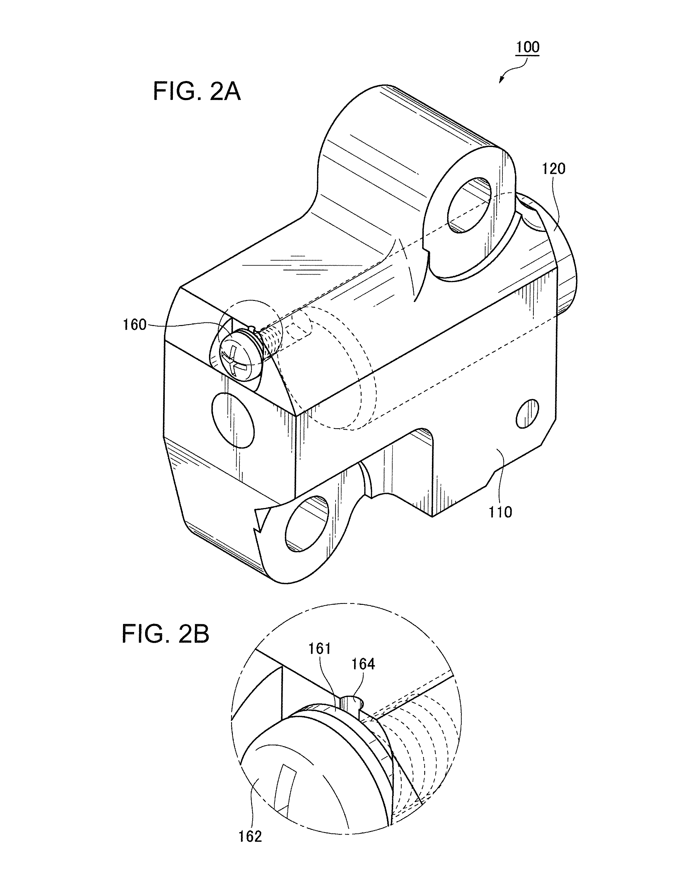
Deaeration of the high pressure oil chamber of a hydraulic tensioner takes place though a helical orifice formed by opposed flanks of the threads of a threaded hole in the tensioner housing and the threads of a screw inserted into the hole. The opposed flanks are maintained in spaced relationship by a force exerted by a spring washer disposed between the head of the screw and a surface of the tensioner housing surrounding the opening of the threaded hole. The flank of the thread of the hole that forms part of the boundary of the helical orifice can have a concave curvature in order to increase the aperture of the air flow path. A groove in the surface surrounding the opening of the threaded hole prevents the washer from sealing off the flow of air. This groove is disposed with its exit end at a level above its entry end.

Description

FIELD OF THE INVENTION[0001]This invention relates to a hydraulic tensioner that applies tension to a timing chain in an engine.BACKGROUND OF THE INVENTION[0002]A hydraulic tensioner applies tension to a timing chain by a plunger that slides in, and protrudes from, a plunger-receiving hole in a tensioner housing, and that, with the housing, forms a high-pressure oil chamber. Oil is introduced under pressure into the high-pressure oil chamber from outside the housing, and the plunger is urged in the protruding direction both by a spring and by hydraulic pressure. An example of a hydraulic tensioner is described in U.S. Pat. No. 5,879,255, granted Mar. 9, 1999.[0003]The tensioner comprises a housing, a cylindrical chamber formed within the housing, a plunger movable axially in the cylindrical chamber, a spring urging the plunger in a protruding direction, a high-pressure oil chamber formed behind the plunger, a oil passage communicating with the high-pressure oil chamber, and a check ...

Claims


Application Information

Patent Timeline
Patent Type & Authority Patents(United States)
IPC IPC(8): F16H7/08
CPCF16H7/0836F16H2007/0806F16H2007/0817F16H2007/0853F16H2007/0859F16H2007/0893
Inventor KUREMATSU, YUJIYOSHIDA, OSAMUMAEDA, MUNEHIROISHII, AKIRA
Owner TSUBAKIMOTO CHAIN CO
Learn More