Infrared imagery device with integrated shield against parasite infrared radiation and method of manufacturing the device

a technology of infrared imagery and shielding, which is applied in the field of infrared imagery devices with integrated shields against parasite infrared radiation, can solve the problem of not being able to integrate additional functions into an optronic system to satisfy genuine operational needs

Active Publication Date: 2015-01-27
COMMISSARIAT A LENERGIE ATOMIQUE ET AUX ENERGIES ALTERNATIVES +1
View PDF13 Cites 3 Cited by
  • Summary
  • Abstract
  • Description
  • Claims
  • Application Information

AI Technical Summary

Problems solved by technology

For a long time, it was impossible to integrate additional functions into an optronic system to satisfy genuine operational needs.

Method used


Image

  • Infrared imagery device with integrated shield against parasite infrared radiation and method of manufacturing the device
  • Infrared imagery device with integrated shield against parasite infrared radiation and method of manufacturing the device
  • Infrared imagery device with integrated shield against parasite infrared radiation and method of manufacturing the device

Examples


Embodiment Construction

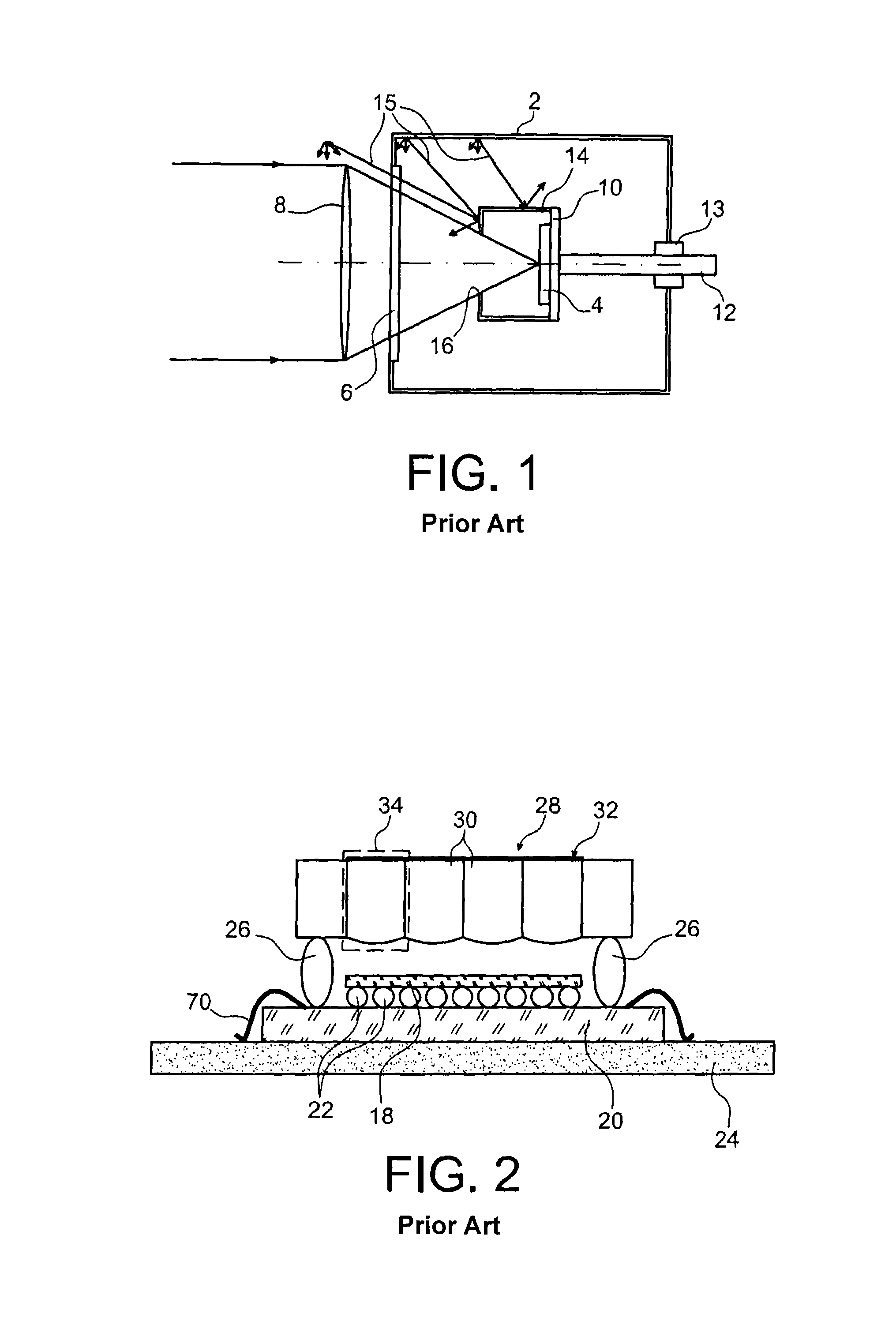
[0076]The following describes various examples of the invention. These examples use the camera on chip that was described with reference to FIG. 2.

[0077]According to the invention, this camera is modified in order to shield it against parasite infrared radiation originating from:[0078]the cryogenic containment or cryostat (not shown) inside which the camera is placed when it is being used, and[0079]what is outside the observation field in the scene facing which the camera is placed.

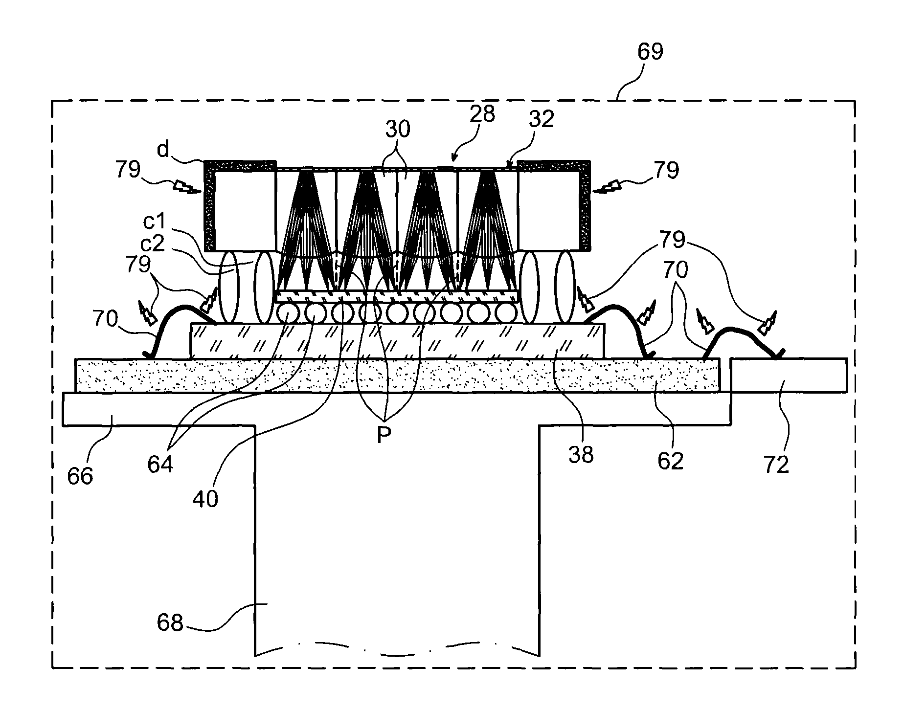
[0080]Frontal parasite infrared radiation is defined as being parasite infrared radiation that can penetrate into the space between the add-on optical device 28 (FIG. 2) and the infrared detection circuit 18 passing through this optical device 28.

[0081]Lateral parasite infrared radiation is also defined as being parasite infrared radiation that can penetrate laterally into that space between the large solder balls 26 that were used to hybridise the optical device 28 to the read circuit 20.

[0082]The config...


PUM

PropertyMeasurementUnit
sizeaaaaaaaaaa
residual pressureaaaaaaaaaa
temperatureaaaaaaaaaa

Abstract

Infrared imagery device with integrated shield against parasite infrared radiation, and method of manufacturing the device. This device comprises a support provided with an infrared radiation detector, at least one optical device facing the detector, and a shield against parasite radiation. The shield comprises at least two continuous beads, spaced from each other, extending from the support as far as the optical device, provided with vents and made of a material that significantly attenuates parasite radiation, penetrating laterally between the support and the optical device. The two beads with their vents 15 form a baffle. The device is manufactured using the flip chip technique.

Description

TECHNICAL FIELD[0001]This invention relates to an infrared imagery device with integrated shield against parasite infrared radiation, and a method of manufacturing this device.[0002]It is particularly applicable to the domain of cryogenic cameras; the infrared detector of a camera of this type is cooled to reduce the thermal noise of the images that it outputs; therefore it must be protected from parasite infrared radiation emitted by warm parts of the cryostat inside which the camera is placed.STATE OF PRIOR ART[0003]FIG. 1 shows a diagrammatic sectional view of a known cryostat 2 containing a known cooled thermal camera, namely a cryogenic camera. The inside of the cryostat is put under a vacuum; the residual pressure is typically equal to 10−5 Pa or less. The vacuum is made either once and for all which is the case in the example shown in FIG. 1, or dynamically, using appropriate means not shown.[0004]The cryogenic camera comprises:[0005]an infrared detection device 4 placed in t...

Claims


Application Information

Patent Timeline
Patent Type & Authority Patents(United States)
IPC IPC(8): G01J5/02H04N5/33
CPCH04N5/33H01L2224/16225H01L2224/48227Y10T29/49826
Inventor FENDLER, MANUELDRUART, GUILLAUME
Owner COMMISSARIAT A LENERGIE ATOMIQUE ET AUX ENERGIES ALTERNATIVES
Why Eureka
Try Eureka