
Apparatus for high rotation rate low I/O count phase interpolator

a phase interpolator and high rotation rate technology, applied in the field of phase interpolators, can solve the problems of high i/o count requirements for phase interpolators, affecting circuit layout, signal integrity, pcb layout, and excessive control word length of systems addressing individual phases

Inactive Publication Date: 2015-02-03
AVAGO TECH INT SALES PTE LTD
View PDF2 Cites 7 Cited by
  • Summary
  • Abstract
  • Description
  • Claims
  • Application Information

AI Technical Summary

Benefits of technology

The patent text describes a technique to reduce the number of control bits and I / O count in phase interpolators by optimizing coding schemes. This technique involves partitioning a full 360 degrees of phase rotation into four 90-degree quadrants and using thermometer encoded bits to address each phase. The use of quadrant-based control schemes reduces I / O count and control word length, but may still require additional coding steps during phase rotation, leading to delay and race hazards. The patent text proposes a solution to this problem by introducing a new coding scheme that reduces I / O count and control word length while still providing high resolution and high rate phase rotation. This new coding scheme is designed to optimize the use of available resources and improve the performance of phase interpolators in high-speed applications.

Problems solved by technology

Unfortunately, systems addressing individual phases suffer from excessive control word length as the number of available phases increase to provide high resolution, driving high I / O count requirements on phase interpolators, impacting circuit layout, packaging, signal integrity, and PCB layout.
Unfortunately, this scheme suffers from redundant encoding at 0, 90, 180, and 270 degrees, requiring an additional coding step during phase rotation, introducing delay and race hazards into control circuitry that may give rise to undesirable and unpredictable discontinuities.

Method used


Image

  • Apparatus for high rotation rate low I/O count phase interpolator
  • Apparatus for high rotation rate low I/O count phase interpolator
  • Apparatus for high rotation rate low I/O count phase interpolator

Examples


Embodiment Construction

[0017]The following Detailed Description refers to accompanying drawings to illustrate exemplary embodiments consistent with the disclosure. References in the Detailed Description to “one exemplary embodiment,”“an exemplary embodiment,”“an example exemplary embodiment,” etc., indicate that the exemplary embodiment described can include a particular feature, structure, or characteristic, but every exemplary embodiment can not necessarily include the particular feature, structure, or characteristic. Moreover, such phrases are not necessarily referring to the same exemplary embodiment. Further, when a particular feature, structure, or characteristic is described in connection with an exemplary embodiment, it is within the knowledge of those skilled in the relevant art(s) to affect such feature, structure, or characteristic in connection with other exemplary embodiments whether or not explicitly described.

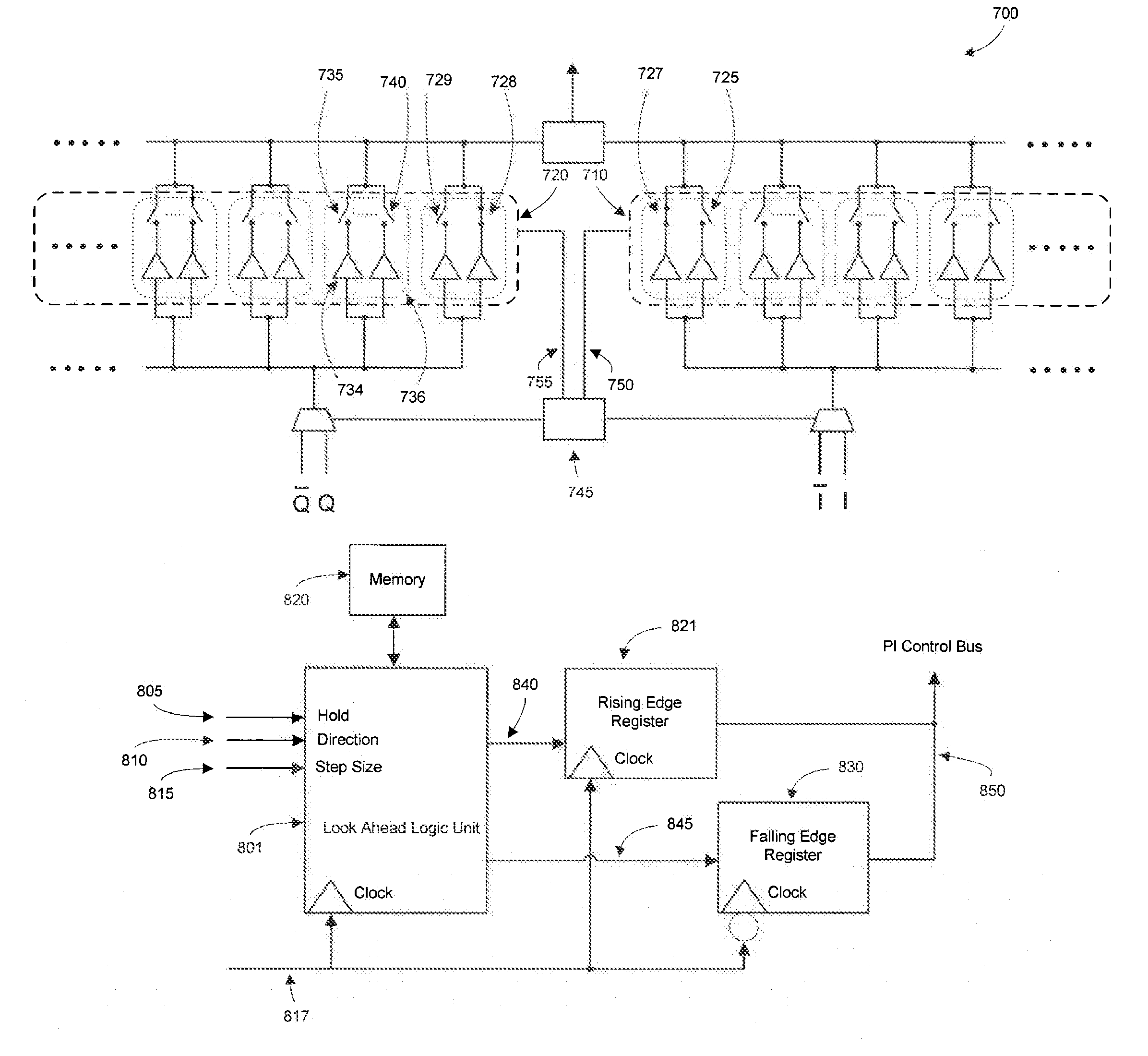
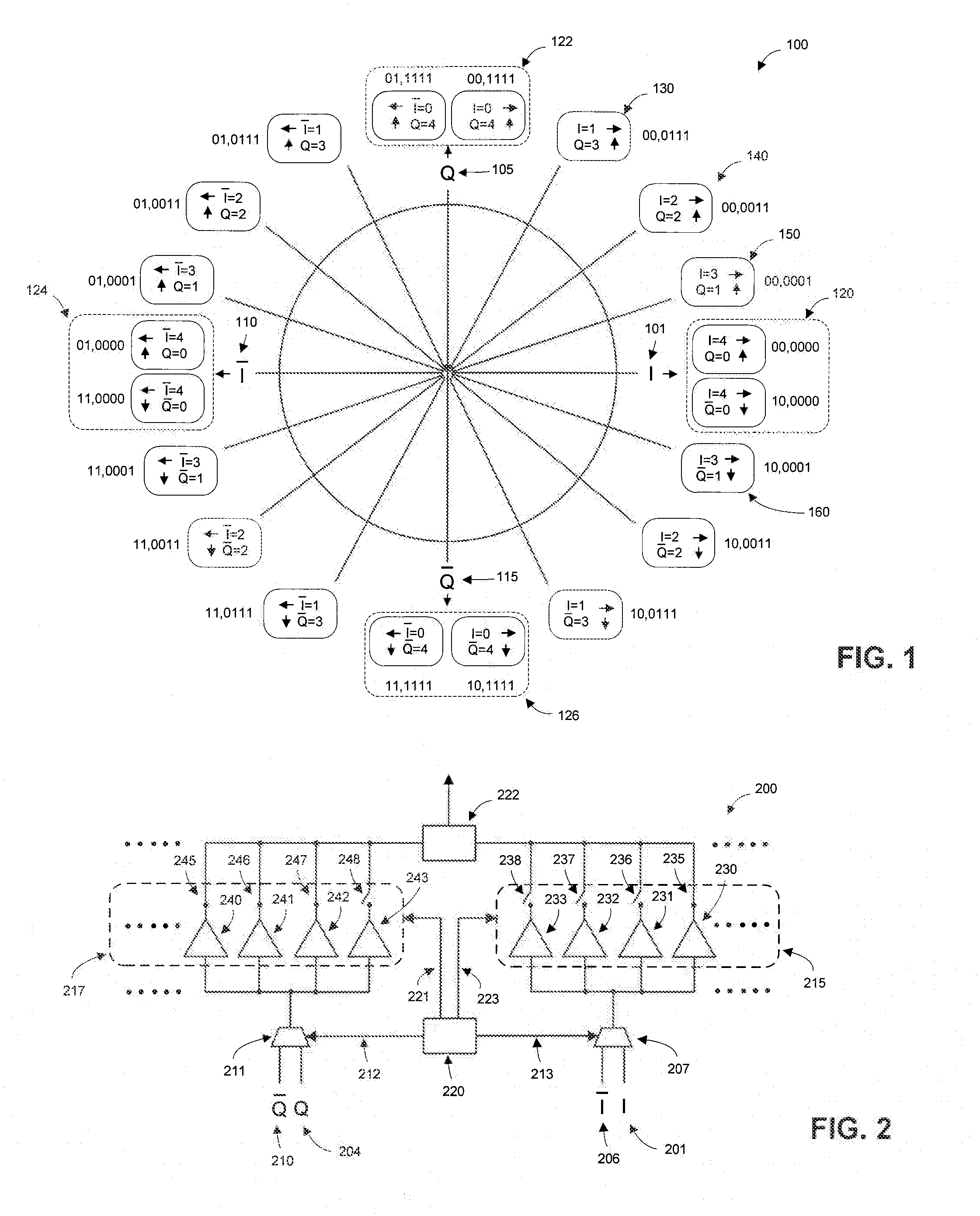
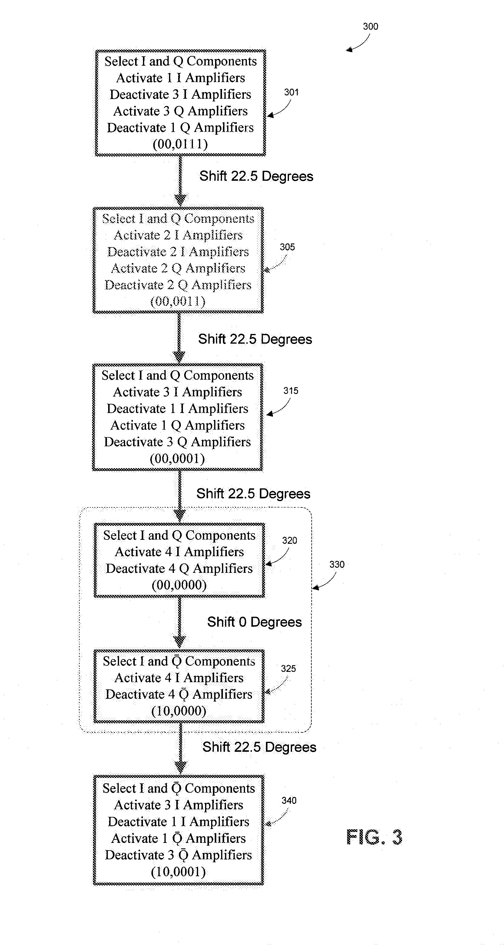
[0018]FIG. 1 illustrates a phase diagram 100 with a phase rotation encoding scheme...


PUM


Abstract

Methods and apparatuses for high rotation rate low I / O count phase interpolation are disclosed, including techniques to reduce redundant phase interpolation coding and method steps by modifying phase mapping and generation with pluralities of amplifiers. I / O reduction count is achieved while maintaining resolution and allowing scalability in phase interpolation. Control circuits include techniques to interpolate phases at a high rotation rate while reducing discontinuities and risk for logic hazards.

Description

BACKGROUND[0001]1. Field of the Disclosure[0002]The disclosure generally relates to phase interpolators, and more specifically to techniques to reduce I / O count and redundant coding in a phase interpolator.[0003]2. Related Art[0004]Recent digital communication standards impose demanding jitter tolerance that requires the use of phase interpolators with high rotation rates and high resolutions. Conventional phase interpolators, including digital control, may include digital control words utilizing thermometer coding schemes addressing each phase individually. Such coding schemes may include Gray coding between adjacent phases allowing single bit changes between adjacent phases, thus allowing high rate phase rotation while avoiding discontinuities due to race hazards within digital control circuits, especially in pipelined and look-ahead applications. Unfortunately, systems addressing individual phases suffer from excessive control word length as the number of available phases increas...

Claims


Application Information

Patent Timeline
Patent Type & Authority Patents(United States)
IPC IPC(8): H03H11/16H03K3/00H04L27/18
CPCH04L27/18
Inventor ZHANG, WEI
Owner AVAGO TECH INT SALES PTE LTD
Learn More