Detecting a servo pattern using a data channel in a magnetic tape drive

Inactive Publication Date: 2015-02-03
IBM CORP
View PDF18 Cites 14 Cited by
  • Summary
  • Abstract
  • Description
  • Claims
  • Application Information

AI Technical Summary

Benefits of technology

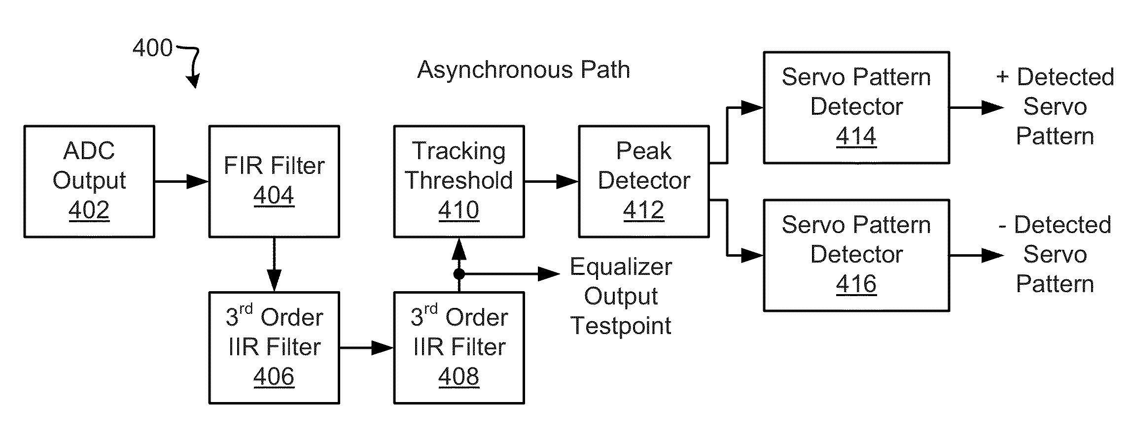
[0007]According to one embodiment, a system for processing data includes an equalizer configured to use servo coefficients for processing servo data and data coefficients for processing non-servo data, wherein the equalizer includes a finite impulse response (FIR) filter configured to process data read with a magnetic tape channel using the servo coefficients to generate equalized data, one or more low-pass filters with aggressive frequency characteristics configured to filter the equalized data to output filtered data, the one or more low-pass filters with aggressive frequency characteristics being configured to remove high frequency noise from the equalized data, a peak detector configured to process peaks in a waveform of the filtered data, and at least one servo pattern detector configured to detect a servo pattern in the filtered data.
[0008]In another embodiment, a magnetic tape drive includes an equalizer configured to use servo coefficients for processing servo data and data coefficients for processing non-servo data, wherein the equalizer includes a FIR filter configured to process data read with a magnetic tape channel using the servo coefficients to generate equalized data, one or more low-pass filters with aggressive frequency characteristi

Problems solved by technology

Firstly, the filter used by the data channel, a 17-tap finite impulse response (FIR) filter, is not sufficient to appropriately filter the servo signals while in the servo pattern detection mode.
Since the frequencies involved with the servo pattern are substantially lower than the frequencies of the data channel, the filtering was not adequate to suppress noise when reading servo patterns with the recording heads.
Se

Method used


Image

  • Detecting a servo pattern using a data channel in a magnetic tape drive
  • Detecting a servo pattern using a data channel in a magnetic tape drive
  • Detecting a servo pattern using a data channel in a magnetic tape drive

Examples


Embodiment Construction

[0029]The following description is made for the purpose of illustrating the general principles of the present invention and is not meant to limit the inventive concepts claimed herein. Further, particular features described herein can be used in combination with other described features in each of the various possible combinations and permutations.

[0030]Unless otherwise specifically defined herein, all terms are to be given their broadest possible interpretation including meanings implied from the specification as well as meanings understood by those skilled in the art and / or as defined in dictionaries, treatises, etc. It must also be noted that, as used in the specification and the appended claims, the singular forms “a,”“an,” and “the” include plural referents unless otherwise specified.

[0031]According to one embodiment, a nominal read data channel is reconfigured for servo pattern detection. One or more infinite-impulse response (IIR) filters are utilized to band-limit a received...


PUM


Abstract

According to one embodiment, a system for processing data includes an equalizer configured to use servo coefficients for processing servo data and data coefficients for processing non-servo data, wherein the equalizer includes a finite impulse response (FIR) filter configured to process data read with a magnetic tape channel using the servo coefficients to generate equalized data, one or more low-pass filters with aggressive frequency characteristics configured to filter the equalized data to output filtered data, the one or more low-pass filters with aggressive frequency characteristics being configured to remove high frequency noise from the equalized data, a peak detector configured to process peaks in a waveform of the filtered data, and at least one servo pattern detector configured to detect a servo pattern in the filtered data. Other systems and methods for processing data are described in more embodiments.

Description

BACKGROUND[0001]The present invention relates to data storage, and more particularly, to detecting a servo pattern of a magnetic tape using a data channel in a magnetic tape drive.[0002]In a magnetic tape drive, data is typically written and read concurrently with 8, 16, 32, or more data channels. The placement of these data channels is determined by the use of servo patterns that are written onto the tape media by the tape manufacturer. The width of the servo pattern is relatively small compared to the width of the tape and the width of the data tracks, with most of the tape space being allocated to the storage of data in the data tracks.[0003]When the tape starts moving from a stopped position, it is important that the magnetic head (which may include multiple different servo heads or readers, magnetic recording heads or writers, and / or magnetic reading heads or readers) be positioned quickly to a correct location with respect to the servo pattern. In past tape drive designs, the ...

Claims


Application Information

Patent Timeline
IPC IPC(8): G11B5/03
CPCG11B20/10G11B5/5926G11B20/10009G11B20/10046G11B5/584G11B20/10037G11B20/1201G11B2005/0013G11B2020/1281
Inventor BLINICK, KATHERINE T.CHERUBINI, GIOVANNIHUTCHINS, ROBERT A.JELITTO, JENS
Owner IBM CORP
Why Eureka
Try Eureka