Heat pump system for vehicle and method of controlling the same

a heat pump and vehicle technology, applied in the direction of vessel parts, instruments, vessel construction, etc., can solve the problems of increasing the operating noise of the compressor b>30/b>, deteriorating or unstable convergence of air discharge temperature in the interior of the vehicle, and passenger dissatisfaction

Active Publication Date: 2015-02-03
HANON SYST
View PDF16 Cites 4 Cited by
  • Summary
  • Abstract
  • Description
  • Claims
  • Application Information

AI Technical Summary

Benefits of technology

[0016]It is another object of the present invention to provide a heat pump system for a vehicle and a method of controlling the heat pump system, which does not operate the compressor just by the number of the maximum revolutions of the compressor but differentiates the upper limit of the number of the maximum revolutions of the compressor according to conditions in the maximum heating mode, thereby reducing a passenger's dissatisfaction caused by a noise of the compressor and enhancing durability of the compressor and stability of the system.
[0019]As described above, the present invention can prevent that convergence of an air discharge temperature of the interior of the vehicle is deteriorated or becomes unstable when the compressor and the electric heater are variably controlled at the same time in order to satisfy the target discharge temperature, because the present invention variably controls only a compressor if the number of revolutions of the compressor is less than the upper limit of the number of the maximum revolutions of the compressor and operates an electric heater only when the number of revolutions of the compressor reaches the upper limit of the number of the maximum revolutions of the compressor in order to satisfy a target discharge temperature in a heat pump mode, thereby
[0020]Moreover, the present invention can reduce a passenger's dissatisfaction caused by a noise of the compressor and enhance durability of the compressor and stability of the system because the present invention does not operate the compressor just by the number of the maximum revolutions of the compressor but differentiates the upper limit of the number of the maximum revolutions of the compressor according to conditions in the maximum heating mode.

Problems solved by technology

However, in order to satisfy a target discharge temperature, the conventional heat pump system for the vehicle variably controls the number of revolutions of the compressor 30 and a heat generation rate of the electric heater at the same time, and hence, the conventional heat pump system for the vehicle has a problem in that convergence of an air discharge temperature in the interior of the vehicle is deteriorated or becomes unstable due to the simultaneous variable control of the number of revolutions of the compressor 30 and the heat generation rate of the electric heater.
Additionally, the conventional heat pump system for the vehicle has another problem in that an operational noise of the compressor 30 is increased because the compressor 30 is operated just at the maximum revolutions in the maximum heating mode and it causes a passenger's dissatisfaction.

Method used


Image

  • Heat pump system for vehicle and method of controlling the same
  • Heat pump system for vehicle and method of controlling the same
  • Heat pump system for vehicle and method of controlling the same

Examples


Embodiment Construction

[0029]Reference will be now made in detail to the preferred embodiment of the present invention with reference to the attached drawings.

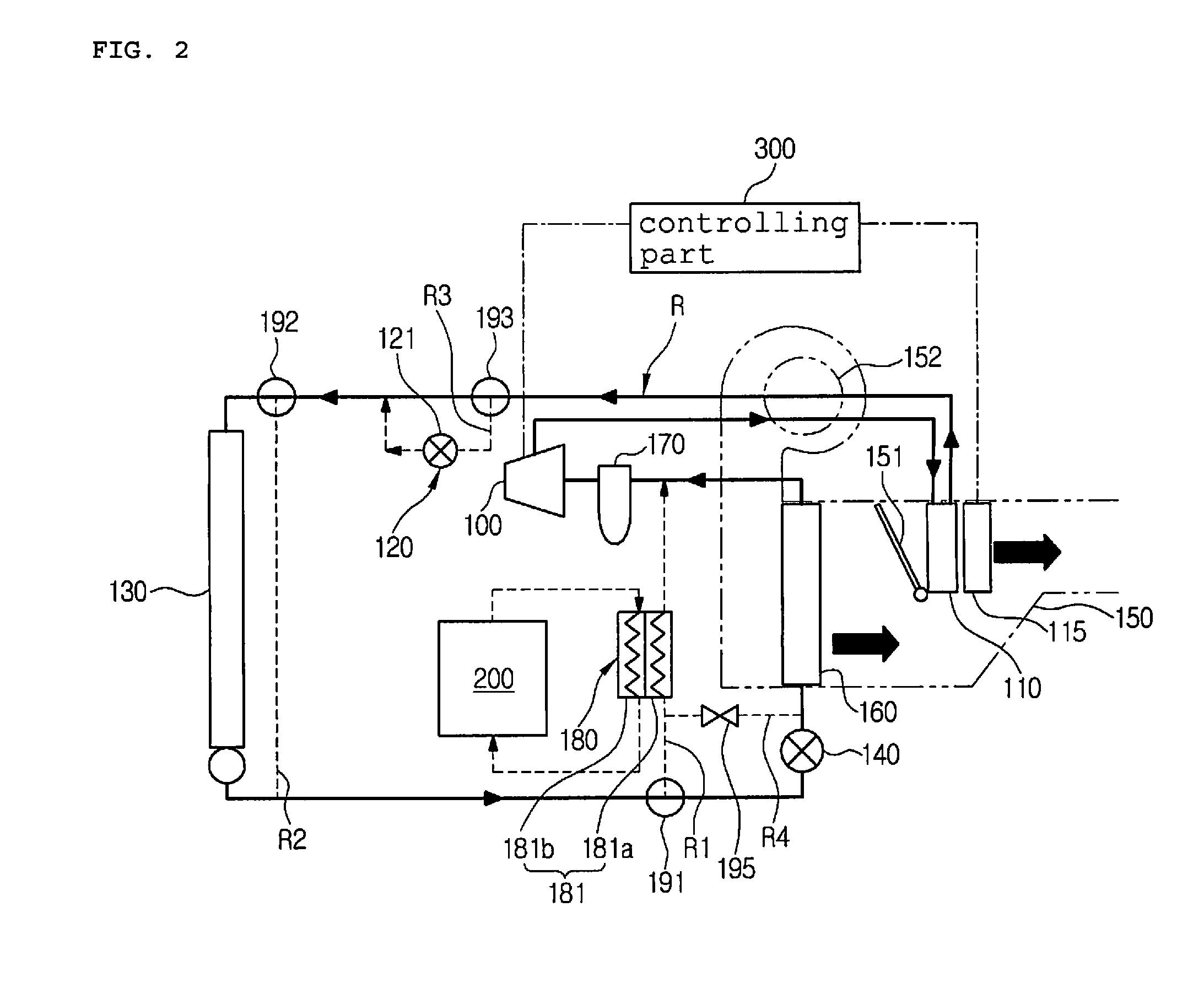
[0030]First, a heat pump system for a vehicle according to the present invention is composed of a compressor 100, an interior heat exchanger 110, second expansion means 120, an exterior heat exchanger 130, first expansion means 140, and an evaporator 160 which are connected on a refrigerant circulation line (R) in order, and is preferably applied to electric vehicles or hybrid vehicles.

[0031]Moreover, on the refrigerant circulation line (R), a first bypass line (R1) bypassing the first expansion means 140 and the evaporator 160, a second bypass line (R2) bypassing the exterior heat exchanger 130, and an expansion line (R3) on which the second expansion means 120 is mounted are respectively connected in parallel. A first direction changing valve 191 is mounted at a branching point of the first bypass line (R1), a second direction changing valve 192 i...


PUM


Abstract

Disclosed therein are a heat pump system for a vehicle and a method of controlling the heat pump system, which variably controls only a compressor if the number of revolutions of the compressor is less than the upper limit of the number of the maximum revolutions of the compressor and operates an electric heater only when the number of revolutions of the compressor reaches the upper limit of the number of the maximum revolutions of the compressor in order to satisfy a target discharge temperature in a heat pump mode, thereby preventing that convergence of an air discharge temperature of the interior of the vehicle is deteriorated or becomes unstable when the compressor and the electric heater are variably controlled at the same time in order to satisfy the target discharge temperature.

Description

[0001]This application claims priority from Korean Patent Application Nos. 10-2012-0021642 filed Mar. 2, 2012 and 10-2013-0020820 filed Feb. 27, 2013, which are hereby incorporated by reference in their entireties.BACKGROUND OF THE INVENTION[0002]1. Field of the Invention[0003]The present invention relates to a heat pump system for a vehicle and a method of controlling the same, and more particularly, to a heat pump system for a vehicle and a method of controlling the heat pump system, which variably controls only a compressor if the number of revolutions of the compressor is less than upper limit of the number of the maximum revolutions of the compressor and operates an electric heater only when the number of revolutions of the compressor reaches the upper limit of the number of the maximum revolutions of the compressor in order to satisfy a target discharge temperature in a heat pump mode, and which does not operate the compressor just by the number of the maximum revolutions of t...

Claims


Application Information

Patent Timeline
Patent Type & Authority Patents(United States)
IPC IPC(8): G06F7/00F25B1/00B60H1/00B60H1/22B60H1/32F25B29/00
CPCF25B29/003B60H1/00921B60H1/2218B60H1/3216B60H2001/3238B60H2001/3261B60H2001/3272
Inventor KIM, TAEEUNKIM, HAKKYUOH, SAEWONLIM, YOUNWOOYOO, SANGJUNLEE, JUNGJAECHOI, YOUNGHOKANG, SUNGHOSEO, JEONGHUN
Owner HANON SYST
Why Eureka
Try Eureka