Method and system for steady state simulation and noise analysis of driven oscillators

a technology of driven oscillator and steady state simulation, applied in the field of electronic circuit characterization and simulation techniques, can solve the problems of indispensibility of circuit simulation tools, many challenges, and insufficient use of conventional circuit analysis and simulation techniques to handle the circuit of driven oscillator

Active Publication Date: 2015-02-03
CADENCE DESIGN SYST INC
View PDF10 Cites 3 Cited by
  • Summary
  • Abstract
  • Description
  • Claims
  • Application Information

AI Technical Summary

Benefits of technology

[0006]Embodiments of the invention provides methods and systems for analysis and simulation of driven oscillators. In some embodiments, a system of equations is formulated for a driven oscillator circuit, in which the frequency of the local oscillator is treated as an extra unknown. With this formulation and the corresponding phase equation, solution techniques, such as multi-tone harmonic balance anal

Problems solved by technology

As circuit size and complexity increase, circuit simulation tools are becoming indispensible.
While some advances have been made in the analysis and simulation of oscillator circuits, many challenges

Method used


Image

  • Method and system for steady state simulation and noise analysis of driven oscillators
  • Method and system for steady state simulation and noise analysis of driven oscillators
  • Method and system for steady state simulation and noise analysis of driven oscillators

Examples


Embodiment Construction

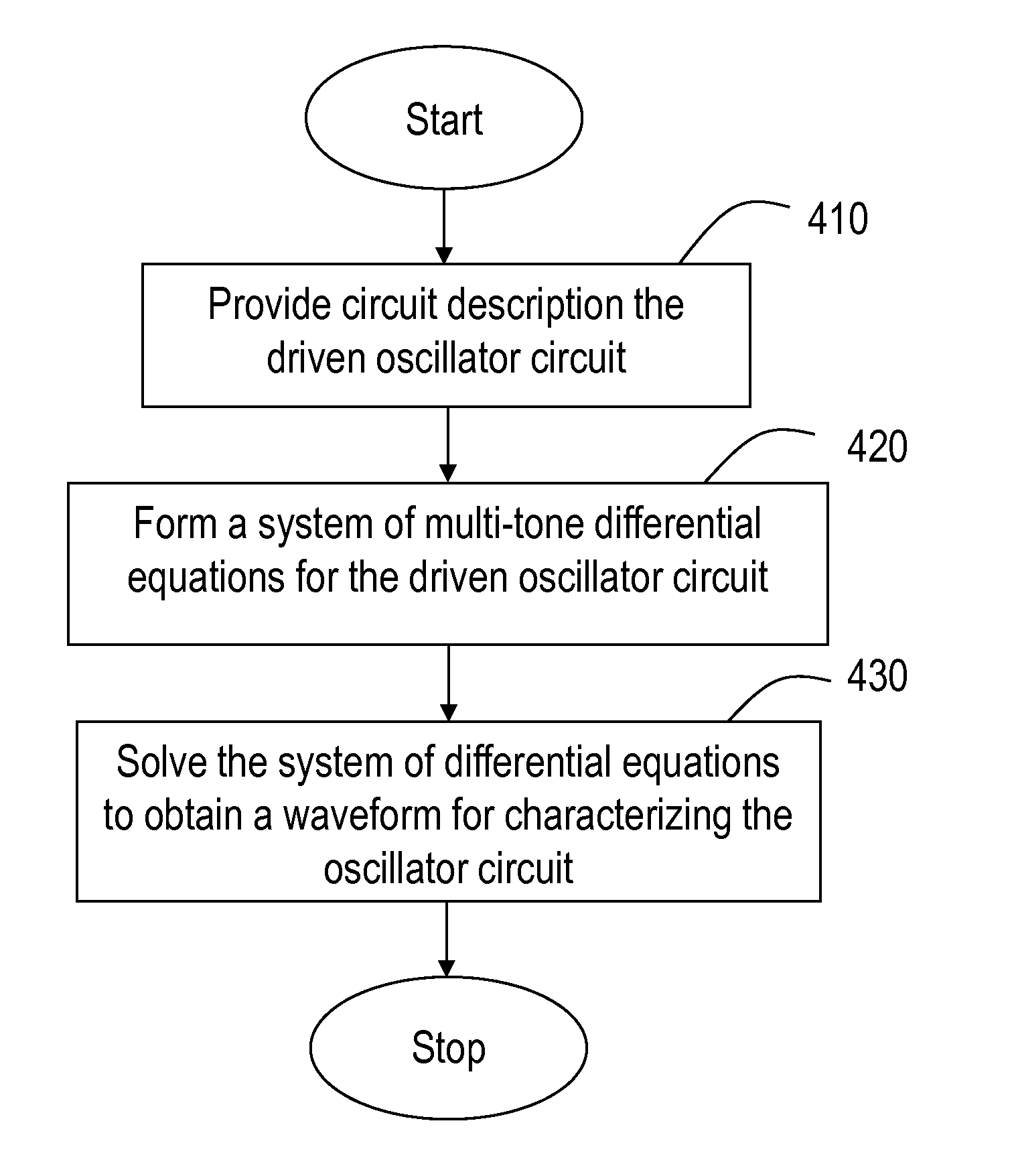
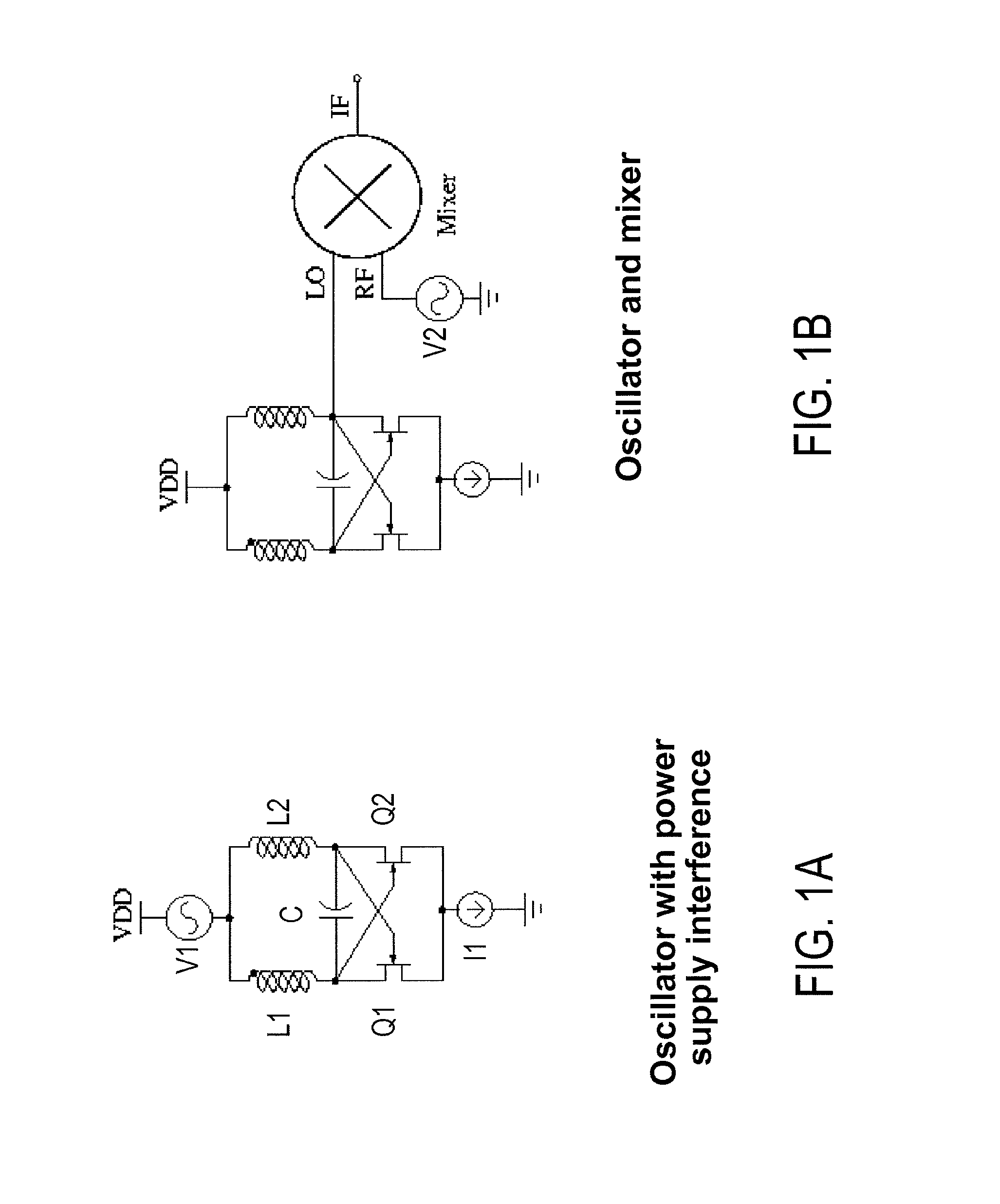
[0022]Modern electronic circuits often include large and complex oscillating systems. In analog designs, oscillators are sometimes driven by periodic signals. An example is the unlocked driven oscillator—the oscillator directly driven by, but not locked to, periodic injection signals. FIG. 1A is a schematic diagram illustrating an oscillator with a periodic interference signal generated from a power supply. In FIG. 1A, the oscillator includes a capacitor C, inductors L1 and L2, cross coupled transistors Q1 and Q2, and a current source I1. In addition, voltage source V1 represents the periodic interference signal from power supply VDD. FIG. 1B is a schematic diagram illustrating a mixer circuit including an oscillator, similar to the oscillator of FIG. 1A, and an RF input signal V2. Such mixer circuits are widely used in communication and signal processing applications.

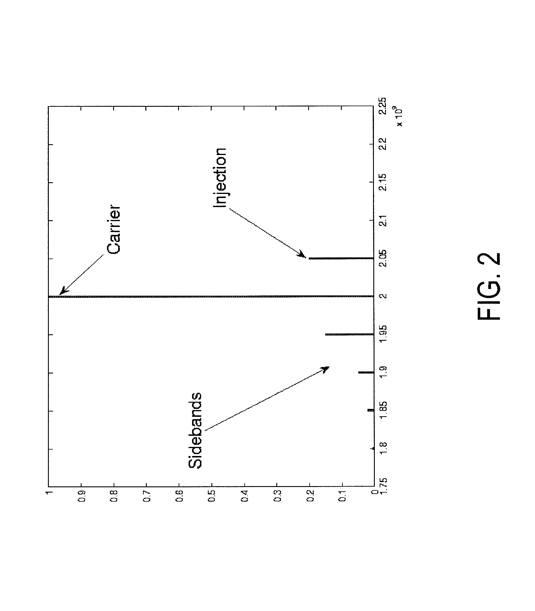
[0023]Unlocked driven oscillators, such as those depicted in FIGS. 1A and 1B, have varying spectra with asymmetric s...


PUM


Abstract

In a circuit simulation tool in a computer system having one or more computer processors and computer-readable storage, a method for characterizing a driven oscillator circuit having an oscillator coupled to a time-varying input signal includes retrieving information provided in a circuit description of the oscillator circuit. The method also includes forming a frequency-domain harmonic balance equation for the oscillator circuit using the retrieved information provided in the circuit description of the oscillator circuit. The harmonic balance equation includes a first differential operator in a frequency domain of the input signal and a product of a differential operator in a second frequency domain of the oscillator and a frequency variable of the oscillator. The frequency variable is independent of the frequency domain of the input signal. The method further includes solving the harmonic balance equation to obtain a waveform description of the oscillator circuit.

Description

CROSS-REFERENCES TO RELATED APPLICATIONS[0001]This application claims priority to U.S. Provisional Application No. 61 / 274,097, filed Jun. 10, 2009, entitled “METHOD AND SYSTEM FOR STEADY STATE SIMULATION AND NOISE ANALYSIS OF DRIVEN OSCILLATORS,” by inventors Xiaolue Lai, et al., commonly assigned, incorporated by reference herein for all purposes.BACKGROUND OF THE INVENTION[0002]The present invention relates generally to electronic circuit characterization and simulation techniques. More particularly, embodiments of the invention provide methods and systems for directly computing waveforms that describe driven autonomous circuits, e.g., a circuit having an oscillator and one or more periodic input signals.[0003]As circuit size and complexity increase, circuit simulation tools are becoming indispensible. In electronic circuit design, a circuit is usually represented by a system of equations, with various circuit components represented by their mathematical models. The models and equ...

Claims


Application Information

Patent Timeline
IPC IPC(8): G06F17/50G01R29/26
CPCG06F30/367
Inventor LAI, XIAOLUEFENG, DANZHU, YU
Owner CADENCE DESIGN SYST INC
Why Eureka
Try Eureka