
Thermal bubble point measurement system and method

a technology of bubble point and measurement system, which is applied in the field of fluid analysis, can solve the problems of dissolved gas segregation into a separate gas phase, the pressure of the bubble point (bp) of the oil, and major blowouts and explosions at a well site, and achieve the effect of improving the bubble point measurement and accurate measurements

Active Publication Date: 2015-02-10
SCHLUMBERGER TECH CORP
View PDF26 Cites 1 Cited by
  • Summary
  • Abstract
  • Description
  • Claims
  • Application Information

AI Technical Summary

Benefits of technology

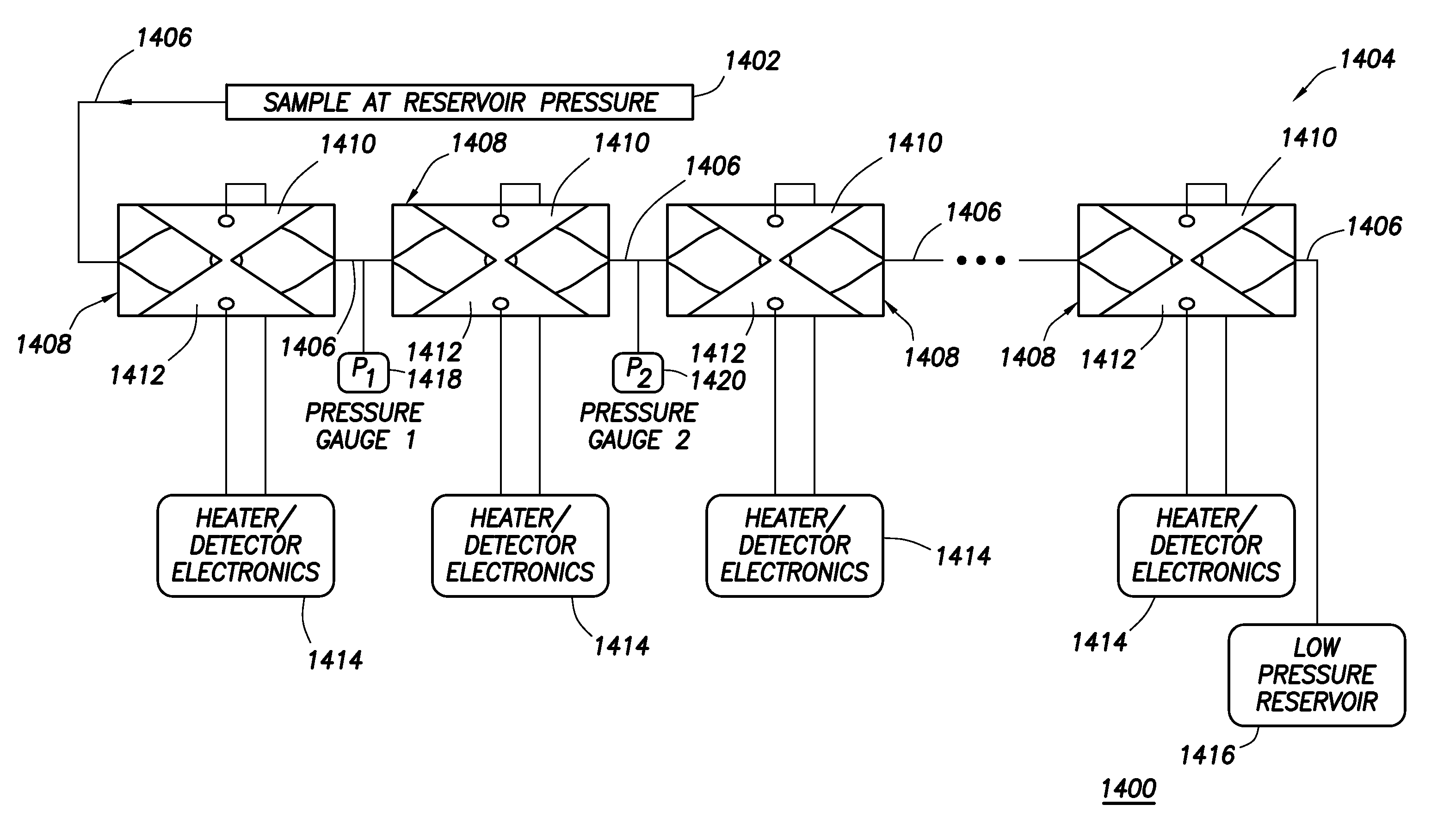
[0010]The present invention provides a method and apparatus for nucleating bubbles in and measuring BP pressure of an oil-gas mixture. Advantageously, the present invention provides controlled bubble nucleation and detection by providing means to define (or e.g., control) the time and the place of nucleation. Such features, when (in some embodiments) coupled with confinement provided by a micro-fluidic environment, allow very accurate measurements to be performed on a bubble subsequent to nucleation, which in turn can lead to improved bubble point measurements.

Problems solved by technology

One particular issue of concern is the bubble point (BP) pressure of the oil.
The pressure of the oil typically drops during the production process, which may cause the dissolved gas to segregate into a separate gas phase.
This process needs to be performed in a very controlled environment, as hydrocarbon gas is highly flammable and compressible, which can lead to major blow-outs and explosions at a well site.
Additionally, the permeability of a gas-oil mixture through a porous rock can be reduced by several orders of magnitude by the presence of bubbles, making production impossible.
Physical size of such a device is important, since integration in a downhole tool imposes stringent limitations on the real estate available.
However, such a measurement can introduce major errors in the determination of bubble point pressure, due to the likely condition of supersaturation.
One way of nucleating bubbles is mentioned in the work cited above of Bostrom et al., demonstrating the use of an ultrasonic transducer to both nucleate bubbles by means of cavitation near the bubble point pressure and detect persistent bubbles; however, such method involves significant sample volumes, and because the nucleation occurs in the bulk of the fluid, the exact position of the nucleated bubbles cannot be controlled.

Method used


Image

  • Thermal bubble point measurement system and method
  • Thermal bubble point measurement system and method
  • Thermal bubble point measurement system and method

Examples


example 1

With Pure Ethanol

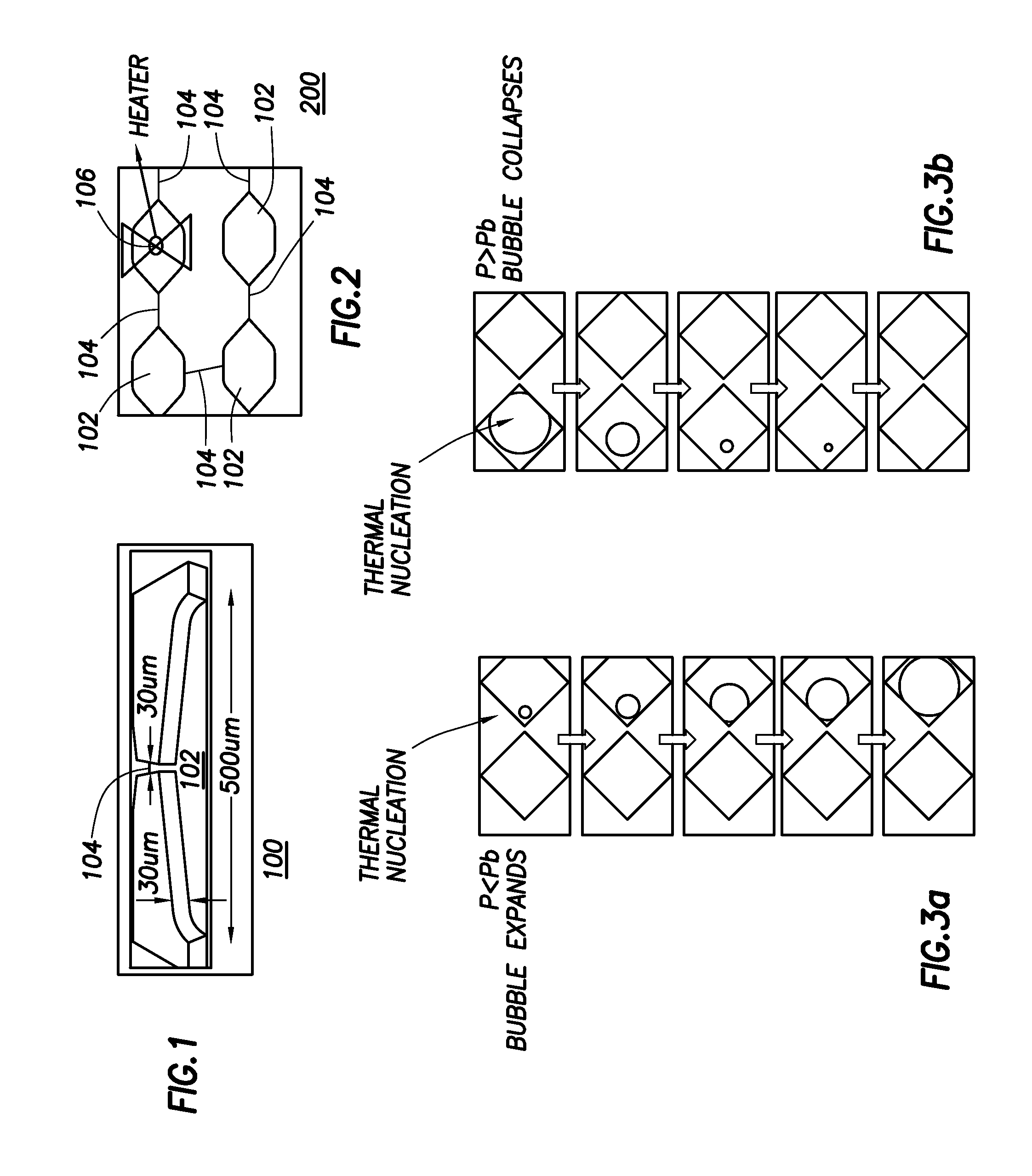
[0051]Exemplary experiments are a simple illustration of the overall principle of the exemplary devices, and were performed at atmospheric and sub-atmospheric pressures using ethanol as the working fluid. Micrographs of the thermal bubble nucleation process using ethanol as the sample fluid are shown in FIG. 7. In FIG. 7, bubble nucleation by heating with the exemplary micro-fabricated heater is shown with a heating power of approximately 500 mW continuously applied to the heater 106, and with the images spaced 10 milliseconds apart. The ethanol was thoroughly degassed in a vacuum dessicator prior to performing any experiments. This allowed a large portion of the dissolved gas (e.g., mostly air) to escape; some dissolved gas remained in the ethanol. The ethanol was injected in the exemplary device, described above in conjunction with FIGS. 1-3, and 5-7, which was in turn connected to a vacuum pump allowing the ambient pressure to be controlled. Using a thermal pulse...


PUM

PropertyMeasurementUnit
sizeaaaaaaaaaa
sizeaaaaaaaaaa
sizeaaaaaaaaaa

Abstract

A method and an apparatus for nucleating bubbles in an oil-gas mixture, including introducing a sample comprising an oil-gas mixture into a chamber; and heating the sample with a heater until at least one bubble is thermally nucleated in the chamber. The bubble point (BP) pressure of the sample can be determined by detecting pressure at two points in a system, which includes the chamber and the heater, and by determining the behavior of the nucleated bubble as the pressure on the bubble is varied.

Description

CROSS REFERENCE TO RELATED DOCUMENTS[0001]The present invention claims benefit of priority to U.S. Provisional Patent Application Ser. No. 61 / 016,457 of Dan ANGELESCU et al., entitled “THERMAL BUBBLE POINT MEASUREMENT SYSTEM AND METHOD,” filed on Dec. 22, 2007, the entire content of which is hereby incorporated by reference herein.BACKGROUND OF THE INVENTION[0002]1. Field of the Invention[0003]The present invention generally relates to fluid analysis, and more particularly to a thermal bubble point measurement system and method.[0004]2. Discussion of the Background[0005]Fluid analysis is of utmost importance to the oilfield industry. Production decisions for a new well are largely based on measurements of fluid properties, either performed downhole (e.g., directly on the reservoir fluids) or in the lab (e.g., on a sample acquired downhole). Information regarding the chemical composition, phase diagram (e.g., including information on the amount of dissolved gas), density and viscosit...

Claims


Application Information

Patent Timeline
Patent Type & Authority Patents(United States)
IPC IPC(8): G01N1/00G01N33/28
CPCG01N33/2823E21B49/0875
Inventor ANGELESCU, DANSULLIVAN, MATTHEWHARRIGAN, EDWARD
Owner SCHLUMBERGER TECH CORP
Learn More