Skiving tool comprising cutter bars

a technology of cutting tools and cutter bars, which is applied in the direction of gear teeth, manufacturing tools, manufacturing apparatuses, etc., can solve the problems of increasing tool cost, affecting productivity, and unsatisfactory life of known skiving tools b>10/b>, and achieves significant potential in machining time, high performance, and fast cycle time

Inactive Publication Date: 2015-02-10
KLINGELNBERG AG
View PDF9 Cites 17 Cited by
  • Summary
  • Abstract
  • Description
  • Claims
  • Application Information

AI Technical Summary

Benefits of technology

[0025]It is an object of the present invention to provide a tool for the cutting machining of the tooth flanks of a tooth wheel or another periodic structure, which is robust and adaptable. Increase in the life of the tool and reduction of manufacturing cost per tooth wheel or per work piece is also an objective of the present invention. This object is solved by a tool according to the present invention, which is herein called a “skiving” tool. The proposed tool shall be suitable for use in series production, for example, in the automotive industry.
[0038]In some embodiments, the cutting edge chip surfaces of the skiving tools are arranged in parallel planes. In some such embodiments, the chip surfaces lie on a cone surface (also called “cone reference surface”), whereby they may be tilted for improving local chipping with respect to the cone reference surface.
[0044]The skiving tools of the present invention also enable high material cutting rates. Additionally, favorable surface structures can be achieved on tooth flanks and other machined surfaces. The machining traces run obliquely across the machined surfaces, which only emits a low noise level during operation, for example, in machining transmission gear elements.
[0046]Skiving using a skiving tool according to the present invention is of high performance, which has significant potential in machining time. In addition to the fast cycle times, tool cost is relatively low. All these aspects contribute to the particular cost effectiveness of skiving with the skiving tools of the present invention.

Problems solved by technology

One problem that arises is that the life of known skiving tools 10 is partly unsatisfactory.
Such interruptions have a negative impact on productivity.
In addition, tool cost increases when the skiving tool 10 must be reground or even exchanged.

Method used


Image

  • Skiving tool comprising cutter bars
  • Skiving tool comprising cutter bars
  • Skiving tool comprising cutter bars

Examples


Embodiment Construction

[0081]In the present description, terms are used which also find use in relevant publications and patents. It is noted however, that the use of these terms shall merely serve a better comprehension. The inventive idea and the scope of the claims shall not be limited in their interpretation by the specific selection of the terms. The invention can be transferred without further ado to other systems of terminology and / or technical areas. In other technical areas, the terms are to be employed analogously.

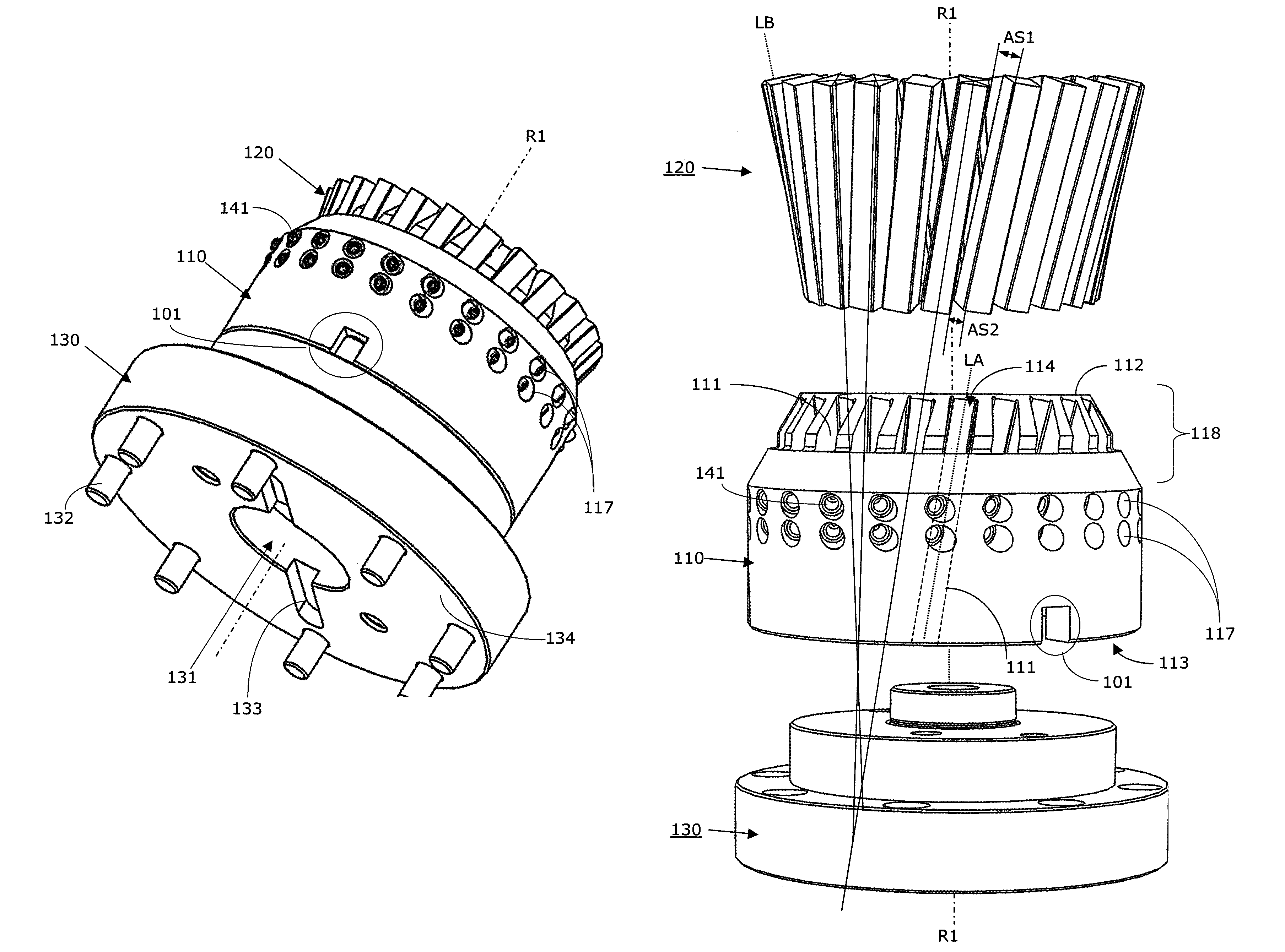
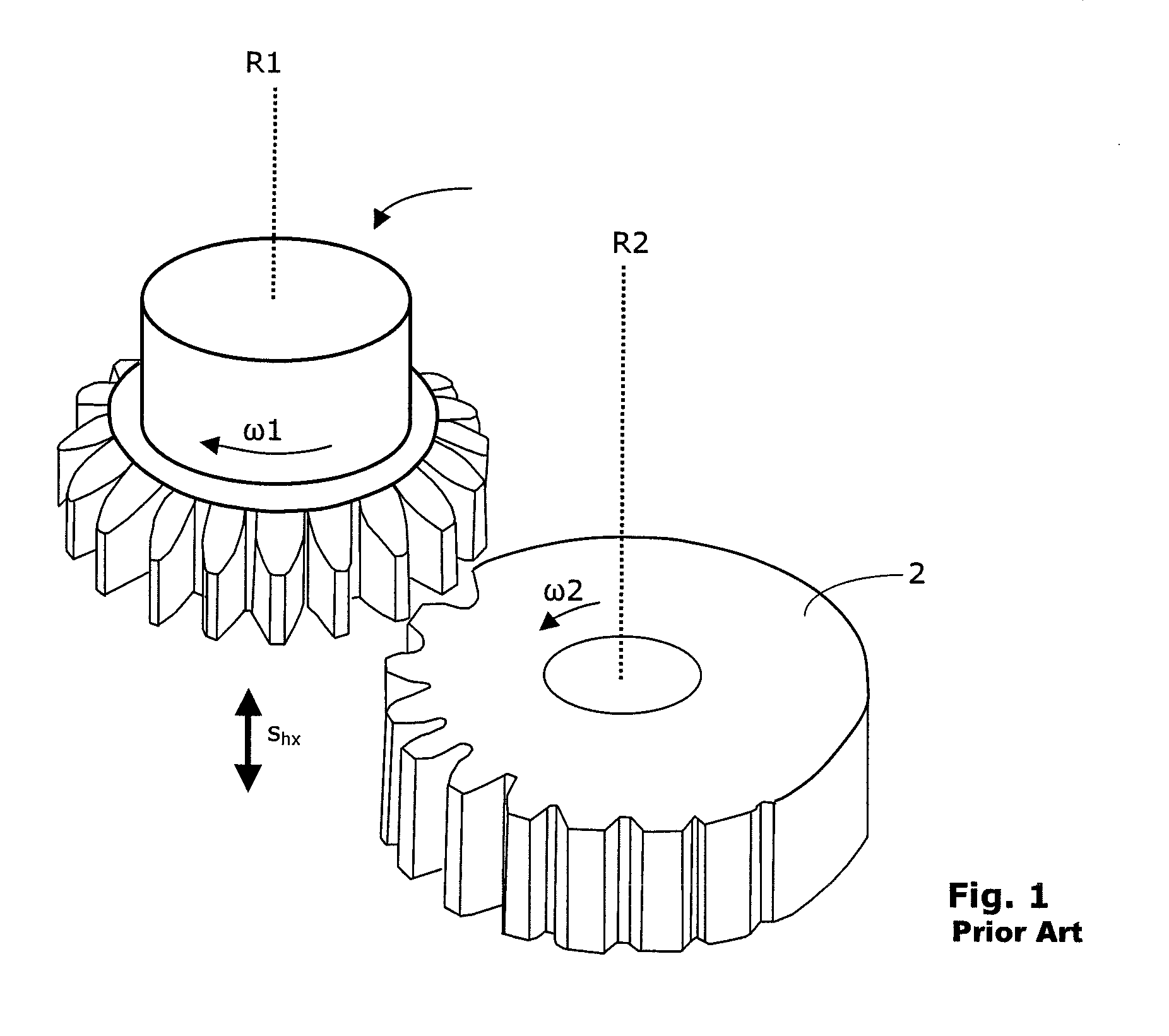
[0082]Rotational-symmetric periodic structures are, for example, gear wheels having an inner and / or outer toothing. However, for example, brake discs, clutch or gear transmission elements, etc., may also be implied. The skiving tools are particularly suitable for the manufacturing of pinion shafts, worms, ring gears, toothed wheel pumps, ring joint hubs (ring joints are employed, for example, in the motor vehicle sector for transmitting the force from a differential gear to a vehicle w...


PUM

PropertyMeasurementUnit
lengthaaaaaaaaaa
lengthaaaaaaaaaa
intersection angleaaaaaaaaaa

Abstract

A skiving tool for manufacturing a rotationally symmetrical periodical structure on a work piece by means of a power skiving method. The skiving tool comprises a base body comprising a central rotation axis and a plurality of receiving openings and a plurality of cutter bars, fewer than or equal to the number of receiving openings. Each of the receiving openings has an elongate shape having a longitudinal axis, and the receiving openings can be arranged uniformly around the central rotation axis. The longitudinal axes of the receiving openings are generators of a rotation hyperboloid, which is arranged rotationally symmetrical to the central rotation axis.

Description

CROSS-REFERENCE TO RELATED APPLICATION[0001]This application claims priority under 35 U.S.C. §§119(a)-(d) to German Patent Application DE 202011050054.3, filed on May 6, 2011, which is hereby incorporated by reference in its entirety as part of the present disclosure.FIELD OF THE INVENTION[0002]The present invention relates to a skiving tool with cutter bars. The skiving tool is designed for manufacturing a rotationally symmetric, periodic structure on a work piece by means of a skiving method.BACKGROUND OF THE INVENTION[0003]There are numerous methods for manufacturing gear wheels. In chip-producing soft pre-machining, one distinguishes hobbing, gear shaping, generating planing and power skiving. Hobbing and power skiving are so-called “continuous” methods, as shall be explained further below.[0004]In the chip-producing manufacturing of gear wheels, one distinguishes between the intermitted indexing process or single indexing process and the continuous method, which may also be cal...

Claims


Application Information

Patent Timeline
Patent Type & Authority Patents(United States)
IPC IPC(8): B23B5/16B23B1/00B23F5/16B23F21/10B23F21/12
CPCB23F5/163B23F21/106B23F21/128Y10T409/101749Y10T409/105724Y10T409/100159Y10T409/105088Y10T82/16114Y10T407/17B23F21/06
Inventor MARX, HARTMUTVOGEL, OLAFZAGROMSKI, MARTIN
Owner KLINGELNBERG AG
Why Eureka
Try Eureka