Supercharge Your Innovation With Domain-Expert AI Agents!

Anti back-drive couplings

a coupling and anti-back-drive technology, applied in the direction of couplings, mechanical actuated clutches, interlocking clutches, etc., can solve the problems of high friction loss, inconvenient production, and inability to drive back-up,

Active Publication Date: 2015-02-10
ROTORK CONTROLS LTD
View PDF7 Cites 17 Cited by
  • Summary
  • Abstract
  • Description
  • Claims
  • Application Information

AI Technical Summary

Benefits of technology

This patent describes a mechanism that prevents a device from spinning in two different directions. When torque is applied in one direction, a part engages with a freewheel that stops the device from spinning. When torque is applied in the other direction, a different part engages with the freewheel to stop the device from spinning. This mechanism ensures that the device can only spin in one direction, making it safer and more controllable.

Problems solved by technology

If the helix angle of the worm gear teeth is shallow, then no back driving is possible.
However, such drives have high friction loses, are expensive to produce, and are not compact.

Method used


Image

  • Anti back-drive couplings
  • Anti back-drive couplings
  • Anti back-drive couplings

Examples


Embodiment Construction

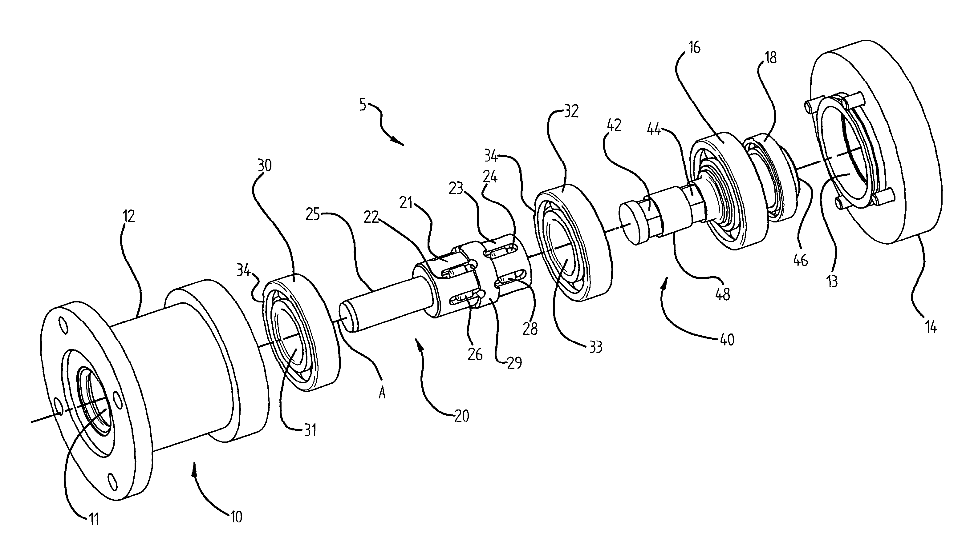
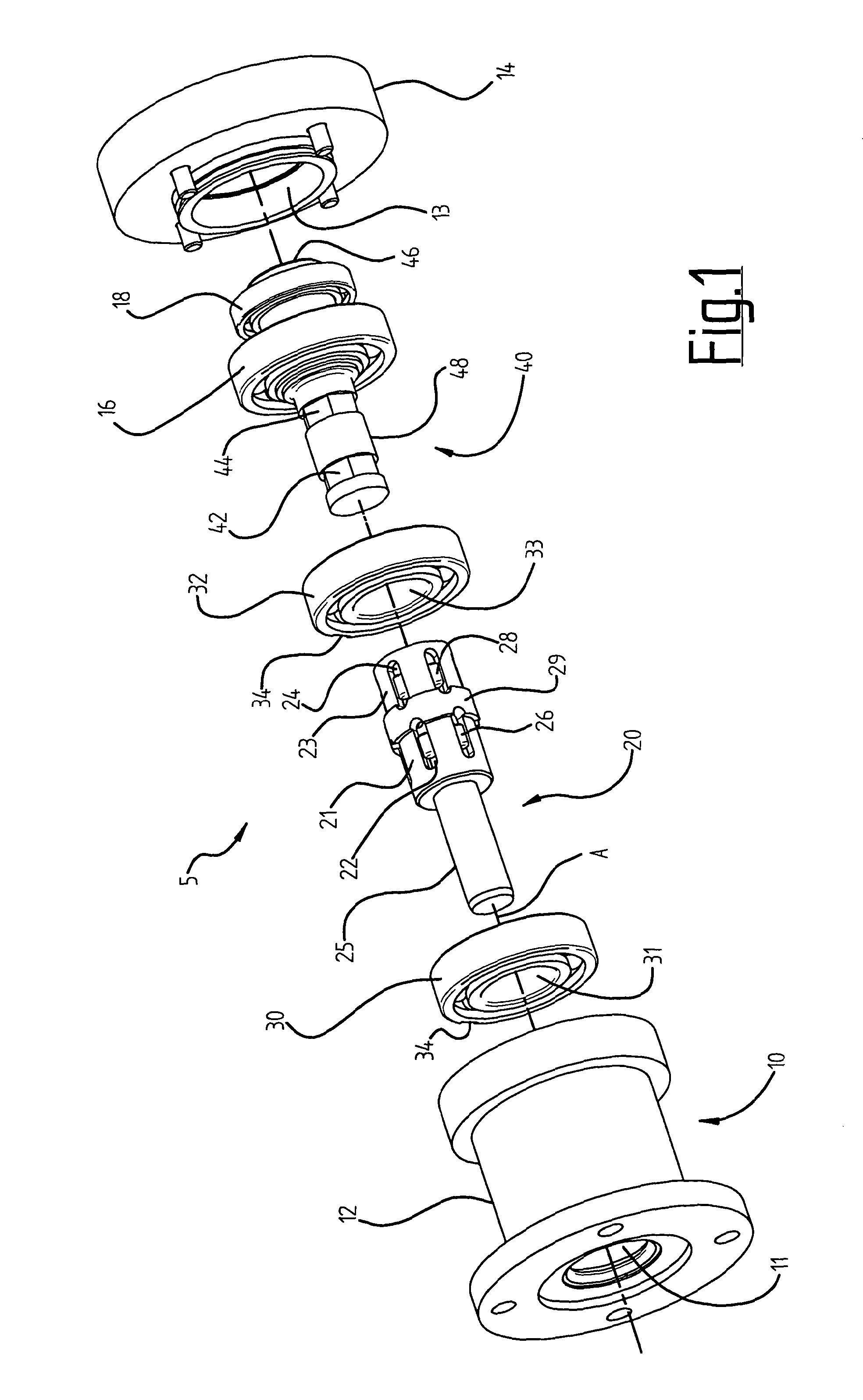
[0021]Referring to FIG. 1 there is shown an exploded view of an anti-back drive coupling 5. The coupling 5 includes a static housing 10 comprising two parts—a body 12 for housing the remaining parts of the coupling and a base 14 for securing to a torque reacting member (not shown) such as a machine frame.

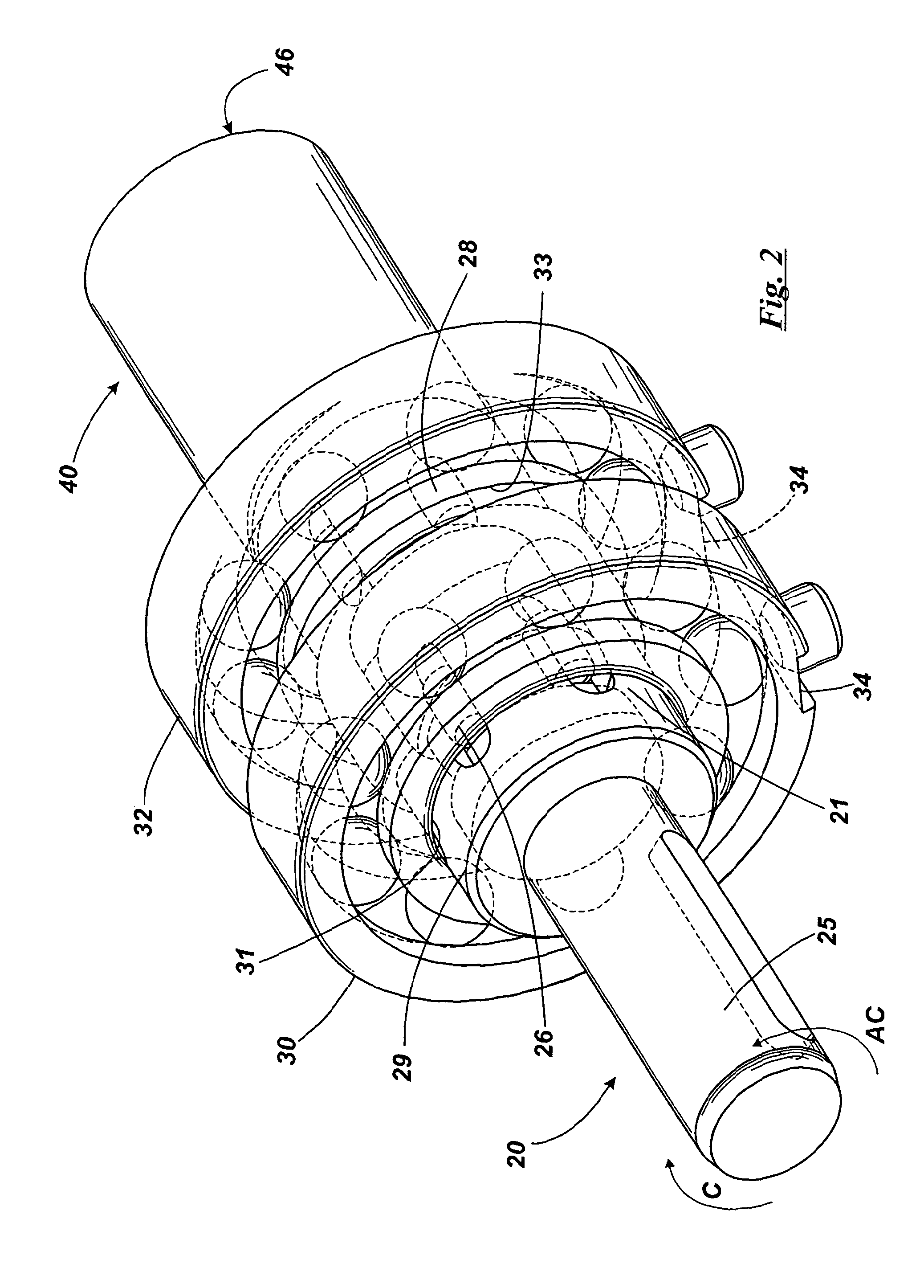
[0022]The coupling 10 further includes an input shown generally at reference 20 and an output shown generally at reference 40 and a mechanism, described below, connecting the input and output. The mechanism includes an input shaft 25, which in use projects through an aperture 11 in the body 12 of the housing 10 and a socket 46, which when assembled in generally flush with the outer face of an output aperture 13 in the base 14. The mechanism further includes a tube 29 in torque transmitting communication with the input shaft 25. The tube 29 has two cages 21 and 23 spaced axially. The cages include a series of circumferentially spaced apertures 22 and 24, only one aperture in each ser...


PUM


Abstract

An anti back-drive coupling (5) comprises an input (20) driveable about an axis A in a clockwise and anticlockwise direction in torque transmitting communication, via a mechanism, with an output (40) driveable about the axis by the input in either of the rotational directions, the mechanism including: a tube (29), driveable by the input, carrying two cages (21) and (23) spaced along the axis A, each cage housing rollers (26) and (28) respectively; an output member 48 for driving the output (40), including two flattened formations (42) and (44) adjacent each cage in use, for engagement with the rollers (26) and (28) respectively; and a back-torque reaction freewheels (30) and (32) engageable with the rollers, for reacting back-torque transmitted through said output member (48) and into the rollers.

Description

FIELD OF THE INVENTION[0001]This invention relates to an anti back-drive coupling which enables torque to be transmitted from an input to an output in clockwise or anticlockwise rotation directions but restrains or prevents the output from transmitting back-torque from the output to the input in both rotation directions.BACKGROUND OF THE INVENTION[0002]Drives such as a worm gear and worm wheel pair allow torque to be transmitted only from an input shaft connected to the worm gear, and into an output shaft connected to the worm wheel. If the helix angle of the worm gear teeth is shallow, then no back driving is possible. However, such drives have high friction loses, are expensive to produce, and are not compact. In addition the low gear ratio provided by that drive is often not required.SUMMARY OF THE INVENTION[0003]The present invention provides an anti back-drive coupling comprising an input driveable about an axis in a clockwise and anticlockwise direction in torque transmitting ...

Claims


Application Information

Patent Timeline
IPC IPC(8): F16D41/10
CPCF16D41/10F16D41/105
Inventor ADAMS, DAVID LESLIE
Owner ROTORK CONTROLS LTD
Features
  • R&D
  • Intellectual Property
  • Life Sciences
  • Materials
  • Tech Scout
  • Unparalleled Data Quality
  • Higher Quality Content
  • 60% Fewer Hallucinations
Learn More