Substrate processing apparatus and particle adhesion preventing method

a technology of substrate and processing apparatus, which is applied in lighting and heating apparatus, instruments, furniture, etc., can solve the problems of affecting the quality of films, affecting the yield of films, and the inability to completely remove contaminants only by supply, so as to achieve the effect of preventing particles

Active Publication Date: 2015-02-10
TOKYO ELECTRON LTD
View PDF16 Cites 5 Cited by
  • Summary
  • Abstract
  • Description
  • Claims
  • Application Information

AI Technical Summary

Benefits of technology

[0014]The present invention has been made in view of the above-mentioned problems, and it is an object of the present invention to provide a substrate processing apparatus and a particle adhesion preventing method capable of effectively preventing particles from being adhered to a substrate, which will be transferred finally to a processing chamber, for processing thereof, in a stage before the execution of the processing in the processing chamber.

Problems solved by technology

When a process is performed on the wafer with particles adhered, degradation in yield may occur.
Further, in a film forming process, the particles adhered to the surface of the wafer may function as nuclei, so that they may cause degradation in film quality due to growth thereof.
However, it may be impossible to completely remove contaminants only by supplying, e.g., clean air to the transfer chamber via the HEPA filter or ULPA filter.
In spite of the above-mentioned countermeasure, however, it is very difficult to completely remove particles from each chamber of the semiconductor processing apparatus.
However, the technique disclosed in Japanese Patent Laid-open Publication No. 2005-354025 is different from the technique for preventing particles from being adhered to the surface of the wafer in that the disclosed technique removes particles adhered to the wafer by peeling off the particles.
Further, it may be impossible to completely remove particles, even by using the above-mentioned technique, because particles having a smaller size exhibit higher adherence.

Method used


Image

  • Substrate processing apparatus and particle adhesion preventing method
  • Substrate processing apparatus and particle adhesion preventing method
  • Substrate processing apparatus and particle adhesion preventing method

Examples


first embodiment

Substrate Processing Apparatus of First Embodiment

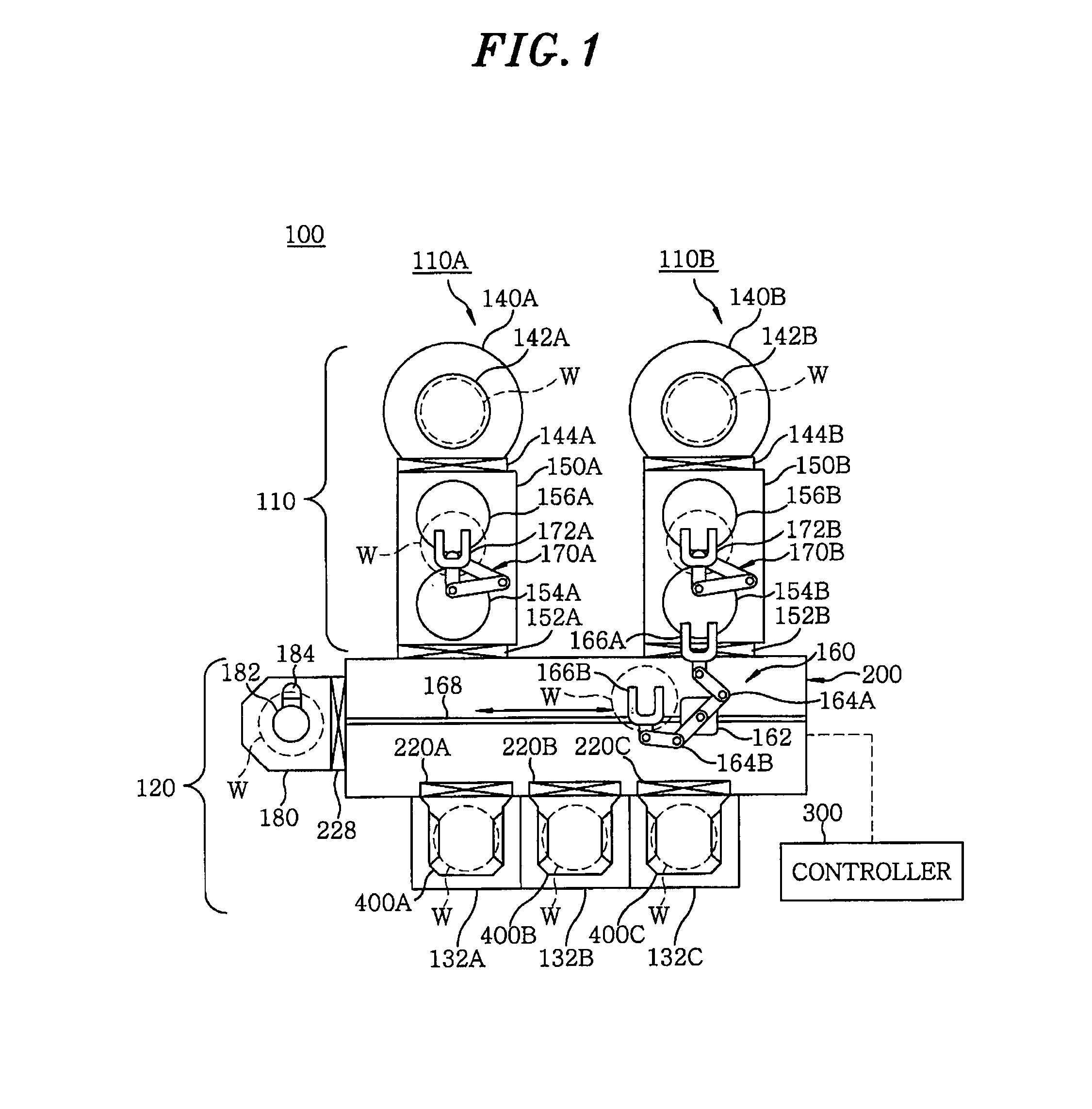
[0077]First, an exemplary configuration of a substrate processing apparatus 100 in accordance with a first embodiment of the present invention will be described with reference to the accompanying drawings. In this case, the substrate processing apparatus 100 includes one, two or more vacuum processing units connected to a transfer chamber. FIG. 1 is a cross sectional view showing a schematic configuration of the substrate processing apparatus 100 in accordance with the first embodiment.

[0078]The substrate processing apparatus 100 includes one, two or more vacuum processing units 110 to perform various processes such as a film forming process or an etching process on a substrate to be processed, e.g., a semiconductor wafer W (hereinafter, also simply referred to as a “wafer”), and a transfer unit 120 to perform loading and unloading of the wafer W with respect to the vacuum processing units 110. The transfer unit 120 includes a transf...

second embodiment

Temperature Control Unit of Second Embodiment

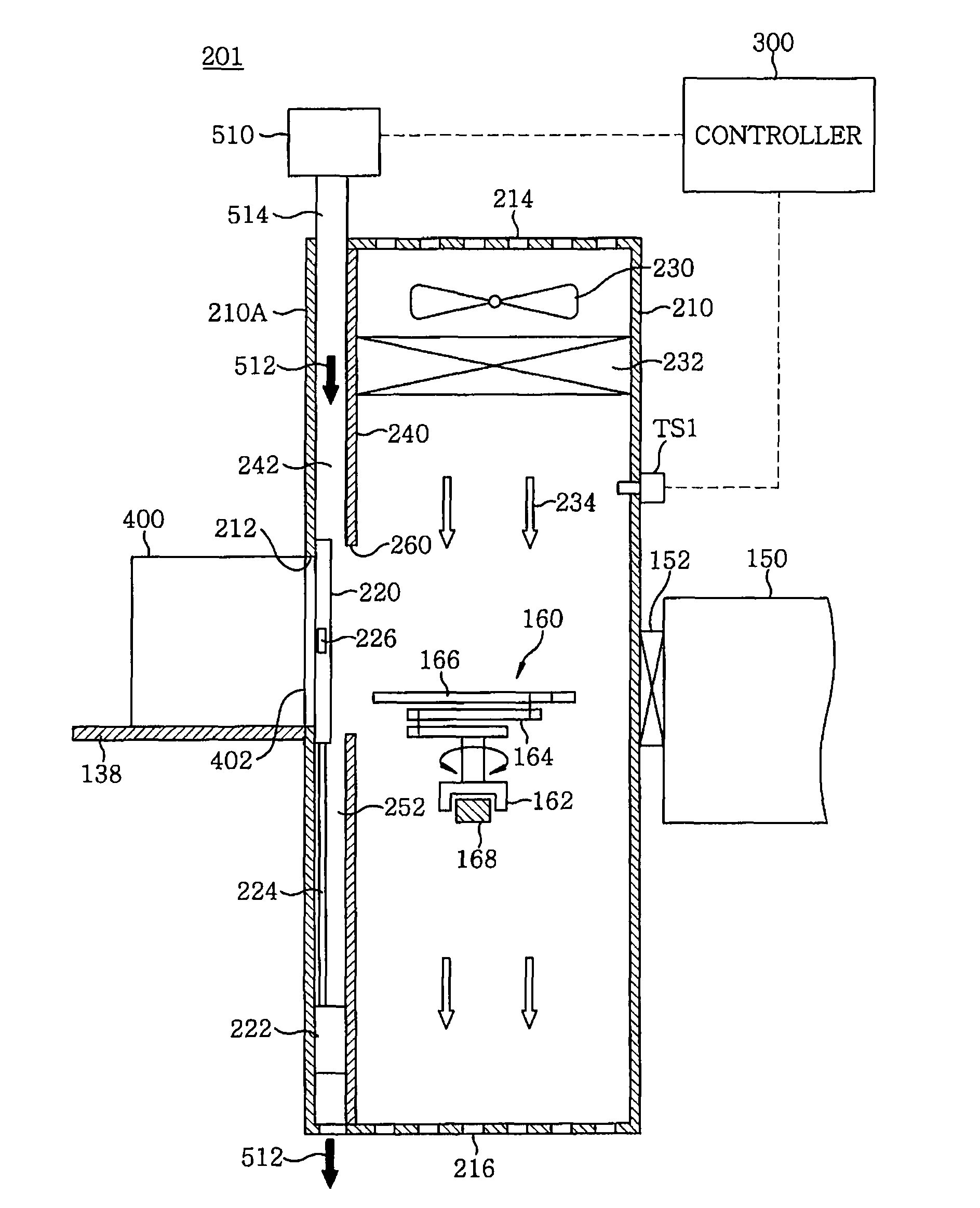
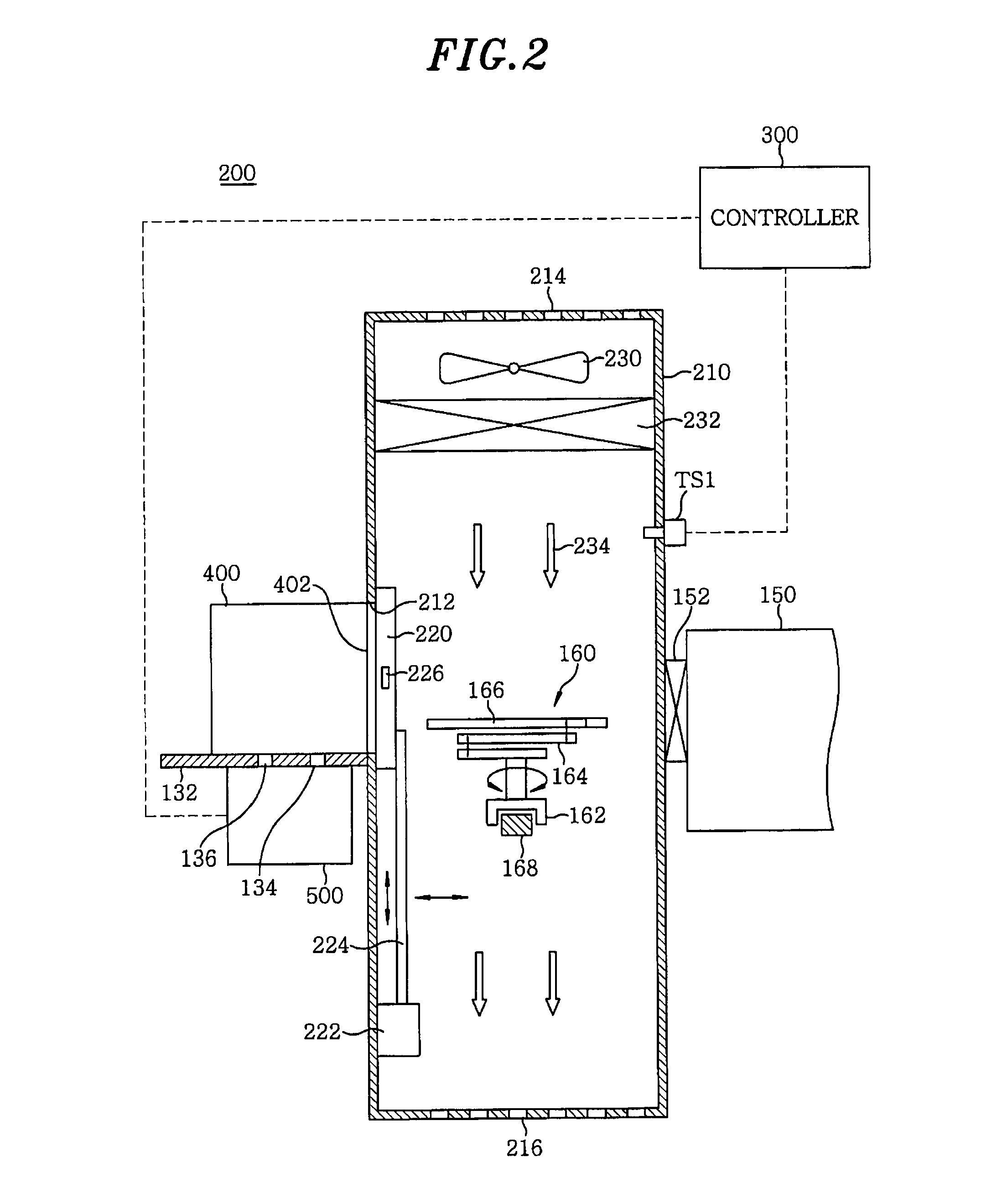
[0137]Hereinafter, a temperature control unit in accordance with a second embodiment of the present invention will be described with reference to FIGS. 11 and 12. In the first embodiment, the temperature control unit that supplies the hot air 502 to the interior of the cassette container 400 through the air holes 404 has been described. However, the second embodiment employs a temperature control unit that supplies hot air to the interior of the cassette container 400 through the substrate gate 212 via an air passage formed in the transfer chamber. Hereinafter, this temperature control unit will be described.

[0138]FIG. 11 is a longitudinal cross sectional view showing a schematic configuration of a transfer chamber 201 including the temperature control unit in accordance with the second embodiment. FIG. 11 is a view taken from one end of the transfer chamber 201. As shown in FIG. 11, an air passage which guides hot air from a hot air supp...

third embodiment

Temperature Control Unit of Third Embodiment

[0152]Hereinafter, a temperature control unit in accordance with a third embodiment of the present invention will be described with reference to FIGS. 13 and 14. In the second embodiment, the case, in which the door moving mechanism including the actuator 222 and the retractable rod 224 is provided in the air passage, has been described. However, the third embodiment employs a door moving mechanism provided at the outside of the air passage. Hereinafter, this configuration will be described.

[0153]FIG. 13 is a longitudinal cross sectional view showing a schematic configuration of a transfer chamber 202 including a temperature control unit in accordance with the third embodiment. FIG. 13 is a view taken from one end of the transfer chamber 202. FIG. 13 illustrates a partition wall 244 extending downwardly from a certain position below the air filter 232, to cover at least the upper end of the substrate gate 212. The partition wall 244 furthe...


PUM


Abstract

Any particle adhesion onto the surface of a substrate to be processed is prevented. There is provided a substrate processing apparatus characterized by including a transfer chamber for, via a gate to which a substrate accommodating container for accommodation of the substrate is set, performing transfer of the substrate between the same and the substrate accommodating container, a processing chamber for applying a specific process to the substrate, a load-lock chamber for linking the processing chamber with the transfer chamber, and a temperature control unit for at the stage of transferring the substrate into at least one of the transfer chamber and the load-lock chamber, so as for the temperature of the substrate just before the transfer thereof to be higher than the temperature of the interior of the chamber, into which the substrate will be transferred, controlling at least one of the temperature of the substrate and the temperature of the interior of the chamber.

Description

FIELD OF THE INVENTION[0001]The present invention relates to a substrate processing apparatus and particle adhesion preventing method capable of preventing adhesion of particles to a surface of a substrate to be processed.BACKGROUND OF THE INVENTION[0002]A substrate processing apparatus is used to perform certain processes such as an etching process or a film forming process on a substrate to be processed such as a glass substrate (e.g., a liquid crystal substrate) or a semiconductor wafer (hereinafter, simply referred to as a “wafer”). The substrate processing apparatus includes, e.g., a processing unit containing a processing chamber for performing a certain process on a wafer, and a load-lock chamber connected to the processing chamber. The substrate processing apparatus further includes a cassette stage, on which a cassette container is placed, the cassette container accommodating an unprocessed wafer to be loaded into the apparatus or a processed wafer to be unloaded from the a...

Claims


Application Information

Patent Timeline
Patent Type & Authority Patents(United States)
IPC IPC(8): H01L21/677H01L21/67
CPCH01L21/67772H01L21/67248H01L21/67766H01L21/67778H01L21/02H01L21/205H01L21/3065H01J37/32522H01J37/34H01J37/3476H01J2237/332H01J2237/334
Inventor TAMURA, AKITAKEHAYASHI, TERUYUKI
Owner TOKYO ELECTRON LTD
Why Eureka
Try Eureka