Display device

a display device and display screen technology, applied in the field of display devices, can solve problems such as attracting many customers, and achieve the effects of fewer components, fewer processes, and reduced costs

Inactive Publication Date: 2015-02-10
LG ELECTRONICS INC
View PDF14 Cites 2 Cited by
  • Summary
  • Abstract
  • Description
  • Claims
  • Application Information

AI Technical Summary

Benefits of technology

[0012]According to the embodiments, the back cover is in direct contact with the front panel, and the back cover and the package main body are fixed to a supporting member, so that the display device can be manufactured with fewer components and lower costs through fewer processes.
[0013]Furthermore, since the front panel forms the entire front exterior of the display device, the front exterior of the display device may seem neat, and the screen of the display device may seem bigger.
[0014]In addition, since the back cover is grounded on the front panel through direct contact with the front panel, the number of connections necessary for electric grounding of the display device can be reduced, and thus the grounding efficiency of the display device can be improved.

Problems solved by technology

Such flat display devices occupy less space owing to its small volume and are light and easy-to-handle, thus attracting many customers.

Method used


Image

  • Display device
  • Display device
  • Display device

Examples


first embodiment

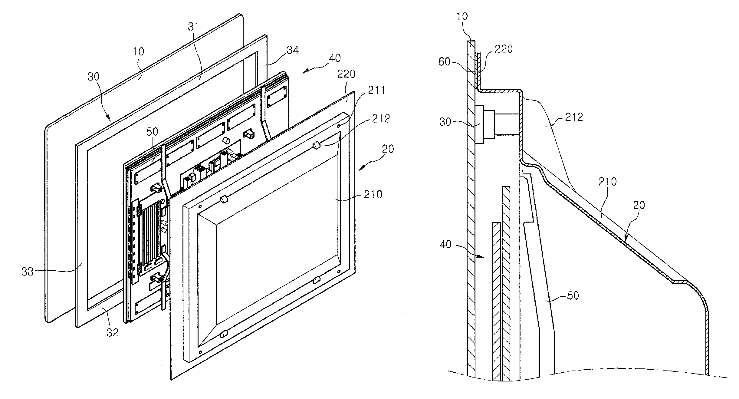
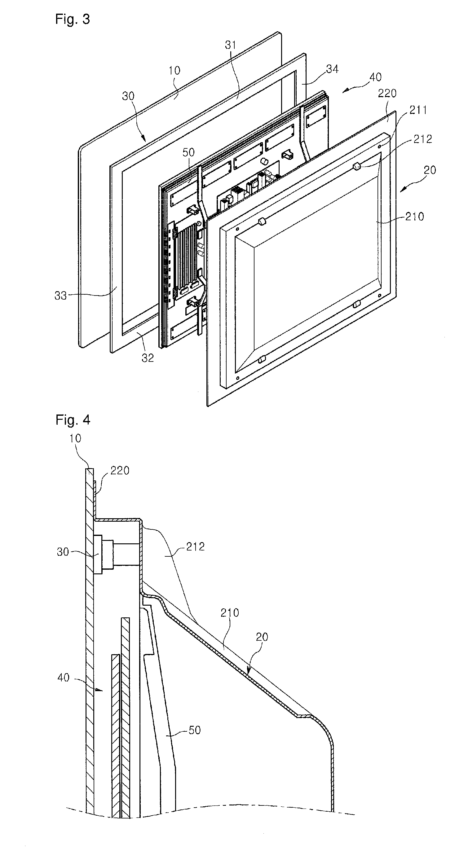
[0028]FIG. 3 is an exploded perspective view illustrating the display device and FIG. 4 is a sectional view taken along line A-A of FIG. 1.

[0029]Referring to FIGS. 3 and 4, the plasma display module 40 is disposed between the front panel 10 and the back cover 20.

[0030]The plasma display module 40 is coupled to a supporting member 30 fixed to the backside of the front panel 10.

[0031]The front panel 10 is formed of glass and is transparent for transmitting images therethrough. The front panel 10 may be formed of toughened glass for satisfying strength requirements of a large display device. However, the front panel 10 can be formed of other materials such as transparent plastic. That is, the front panel 10 can be formed of any materials that are transparent and have allowable strength, and this material modification will be included in the scope of the current embodiment.

[0032]A plurality of layers, such as an antireflection layer, an optical characteristic layer, an electromagnetic ...

second embodiment

[0047]FIG. 5 is a sectional view taken long line A-A of FIG. 1, according to a

[0048]The current embodiment is the same as the first embodiment except for a grounding member disposed between the front panel and the back cover. Thus, in the following description of the current embodiment, the characteristic part will be only described.

[0049]Referring to FIG. 5, in the current embodiment, a grounding member 60 is provided on the backside of the front panel 10. The grounding member 60 is provided at four backside edge portions of the front panel 10. The grounding member 60 may be fixed to the front panel 10 using an adhesive member (e.g., a double-sided tape) or an adhesive.

[0050]The grounding member 60 may be formed of a conductive material such as aluminum or copper. The grounding member 60 may be elastic. For example, the grounding member 60 may be configured by an elastic member (e.g., sponge) and a conductive member (e.g., an aluminum member) surrounding the elastic member. Therefo...

third embodiment

[0056]FIG. 6 is a rear perspective view illustrating a display device and FIG. 7 is a sectional view taken along line B-B of FIG. 6.

[0057]The current embodiment is the same as the first embodiment except for a method of fixing a front panel and a back cover. Thus, in the following description, the characteristic feature will be only described.

[0058]Referring to FIGS. 6 and 7, in the current embodiment, a front panel 10 includes a coupling member 70 for coupling with a back cover 20. The coupling member 70 may be fixed to the backside of the front panel 10 by using an adhesive member (not shown) or an adhesive (not shown).

[0059]The coupling member 70 includes upper and lower coupling members 71 and 72 disposed at upper and lower backside edge portions of the front panel 10, and a lateral coupling member 73 disposed at a right backside edge portion of the front panel 10 and connected to the upper and lower coupling members 71 and 72. In the current embodiment, the lateral coupling me...


PUM


Abstract

A display device is provided. The display device includes a front panel forming a front exterior of the display device and transmitting images therethrough, a back cover forming a rear exterior of the display device and comprising an edge portion making contact with a backside of the front panel, and a display module accommodated in a space formed by the front panel and the back cover.

Description

CROSS-REFERENCE TO RELATED PATENT APPLICATIONS[0001]This application is a U.S National Stage Application under 35 U.S.C. §371 of PCT Application No. PCT / KR2008 / 007654, filed Dec. 24, 2008, which claims priority to Korean Patent Application No. 10-2008-0102543, filed Oct. 20, 2008, whose entire disclosures are hereby incorporated by reference.TECHNICAL FIELD[0002]The present disclosure relates to a display device.BACKGROUND ART[0003]Generally, display devices are used to display images. Recently, many display devices having a two-dimensional flat shape have been introduced into the market. Such flat display devices occupy less space owing to its small volume and are light and easy-to-handle, thus attracting many customers.[0004]Such a display device may include a display module for displaying images. Examples of the display module include a plasma display module.[0005]The plasma display module is operated by using light emitted from a fluorescent material excited by ultraviolet rays ...

Claims


Application Information

Patent Timeline
Patent Type & Authority Patents(United States)
IPC IPC(8): H05K5/00H04N17/00H04N7/14A47G1/10H05K7/00H04N5/64
CPCH04N5/64Y10S248/917Y10S248/918Y10S248/92
Inventor OH, DAE-SUNG
Owner LG ELECTRONICS INC
Why Eureka
Try Eureka