
Spline optic and lighting device

a technology of optical components and lighting devices, applied in semiconductor devices, lighting and heating apparatus, instruments, etc., can solve the problems of difficult to achieve omnidirectional light distribution, poor thermal management, and inability to directly replace incandescent lamps, etc., to achieve the effect of improving thermal management without significantly compromising optical performan

Active Publication Date: 2015-02-10
MASSACHUSETTS DEV FINANCE AGENCY
View PDF1 Cites 70 Cited by
  • Summary
  • Abstract
  • Description
  • Claims
  • Application Information

AI Technical Summary

Benefits of technology

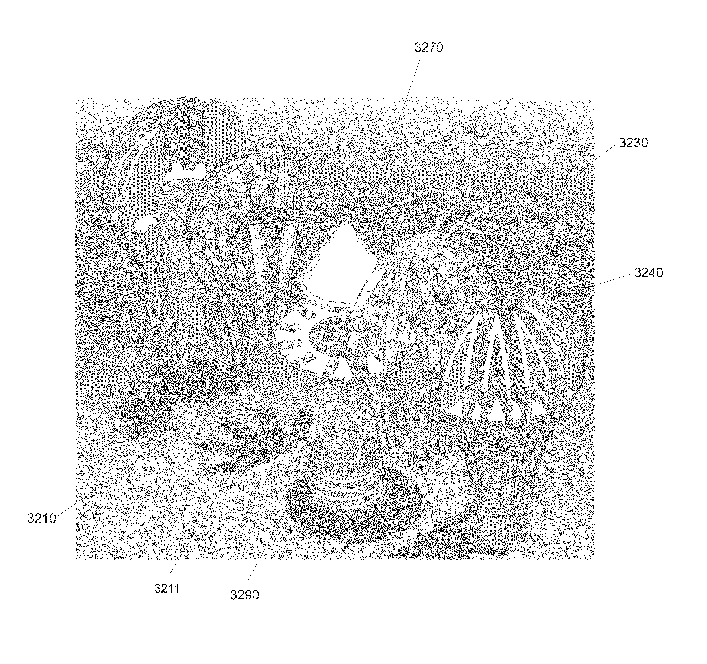
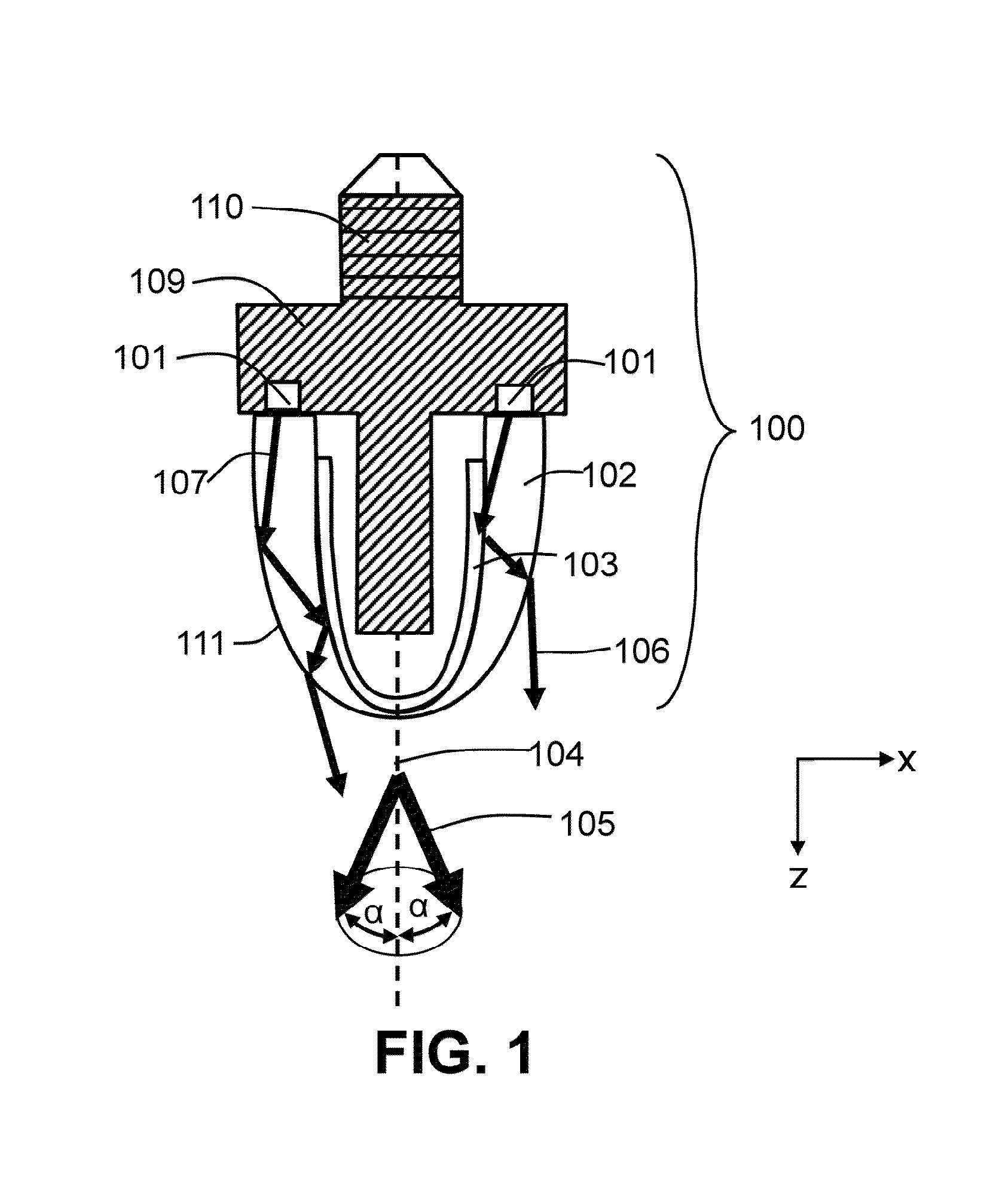
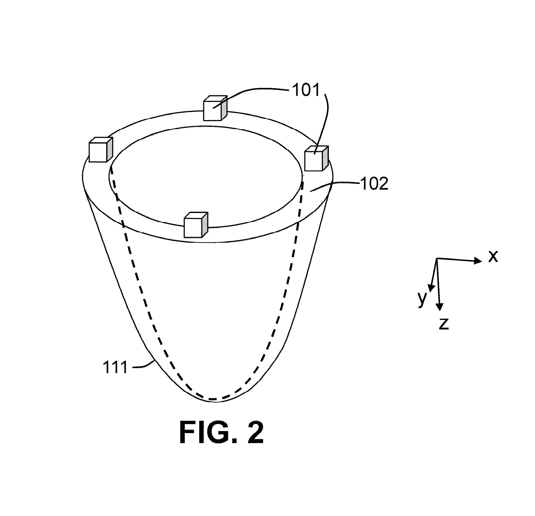
The patent describes a non-planar lamp that combines optical and thermal splines to distribute the output of discrete light sources like LEDs. This results in a uniform and desired light output, like omnidirectional coverage. The integrated thermal splines help manage the heat without affecting the optical performance of the lamp.

Problems solved by technology

However, due to differences in light distribution and non-uniformities in brightness and color, typical LED lamps are not well suited for direct replacement of incandescent lamps.
These lamps have a very wide angle and largely omnidirectional light distribution which is difficult to achieve with typical LED lamps.
However, these lamps are not literally 100% omnidirectional as the bulb geometry of all these types connects to a base which typically blocks light transmission.

Method used


Image

  • Spline optic and lighting device
  • Spline optic and lighting device
  • Spline optic and lighting device

Examples


example 1

[0379]A volumetric light scattering film produced as described in U.S. Pat. No. 5,932,342 is inserted into the cavity of a mold with a quadric surface and held in place by a vacuum. Light transmitting PMMA is injected into the mold such that it is optically coupled to the a surface of the volumetric light scattering film. The mold is cooled and the resulting tapered lightguide with a quadric surface and a polished edge is removed. A light source comprised of an array of light emitting diodes (white Rebel LEDs produced by Lumileds) on a circular metal core annulus is disposed next to the input edge of the lightguide.

example 2

[0380]An anisotropic light scattering diffuser film produced as described in U.S. Pat. No. 5,932,342 is inserted into the cavity of a mold and held in place by a vacuum. A light source comprised of an array of light emitting diodes (white Rebel LEDs produced by Lumileds) on a metal core strip. The diffuser is oriented with the domains substantially parallel to the optical axis of the LEDs. Light transmitting PMMA is injected into the mold such that it is optically coupled to the output surface of the LEDs and the anisotropic light scattering diffuser film. The mold is cooled and the resulting article is removed.

example 3

[0381]Two anisotropic light scattering diffuser films produced as described in U.S. Pat. No. 5,932,342 are inserted onto opposite surfaces of the cavity of a mold and held in place by a vacuum. A light source comprised of an array of light emitting diodes (white Rebel LEDs produced by Lumileds) on a metal core strip. The diffusers are oriented with the domains substantially parallel to the optical axis of the LEDs. Light transmitting PMMA is injected into the mold such that it is optically coupled to the output surface of the LEDs and the anisotropic light scattering diffuser films. The mold is cooled and the resulting article is removed.


PUM


Abstract

Optical and thermal splines are integrated in the external envelope of a non-planar lamp allowing the optical output of discrete light sources such as LEDs to be distributed for uniform output and the achievement of desired light distributions such as omnidirectional output. Integrated thermal splines and perimeter location of light sources allow for improved thermal management without significantly compromised optical performance.

Description

RELATED APPLICATIONS[0001]This application is a continuation-in-part of non-provisional application Ser. No. 13 / 459,249 “LED Light Bulb with Omnidirectional Output” filed Apr. 29, 2012 now U.S. Pat. No. 8,750,671, itself a continuation-in-part of non-provisional application Ser. No. 12 / 762,253 “Arcuate lightguide and light emitting device comprising the same” filed Apr. 16, 2010 now U.S. Pat. No. 8,761,565 which claims the benefit of provisional patent application Ser. No. 61 / 170,038 titled “Arcuate lightguide and light emitting device comprising the same” filed Apr. 16, 2009. Additionally, this application claims the benefit of provisional filing 61 / 503604 titled “Spline Optic and Lighting Device” filed Jun. 30, 2011.FIELD OF THE INVENTION[0002]The invention relates generally to optical components, light emitting devices, LED lamps, and bulbs for illumination applications.BACKGROUND OF THE INVENTION[0003]Compared to conventional incandescent lamps, light emitting diode (LED) lamps ...

Claims


Application Information

Patent Timeline
Patent Type & Authority Patents(United States)
IPC IPC(8): G02B6/43F21V5/04F21V7/04H05B33/02
CPCH05B33/02F21V3/049F21V5/04F21V7/005F21V7/0091F21V7/04F21V2200/15F21V2200/20F21K9/232F21Y2115/10F21V5/10G02B6/10
Inventor KELLY, TIMOTHYYEO, TERENCEMORIN, DAVID
Owner MASSACHUSETTS DEV FINANCE AGENCY
Learn More