Fuel system

Active Publication Date: 2015-02-17
AUDI AG
View PDF19 Cites 3 Cited by
  • Summary
  • Abstract
  • Description
  • Claims
  • Application Information

AI Technical Summary

Benefits of technology

[0008]It is therefore the object of the invention to propose a fuel system which has a lower energy consumption wherein in particular a decrease of the

Problems solved by technology

As a result of the high pressure or the great pressure difference between the pressure inside the fuel tank and the pressure outside of the fuel tank, the ventilated fuel has high flow velocities, which causes liquid fuel to be carried along by the gaseous fuel.
Here, however, a rise of the fill level of the temporary accumulator may result for example due a limitation of the discharge volume flow, in particular by a line cross section or the like.
When operating the fuel system, the amount of liquid fuel present in the temporary accumulator or the separation devic

Method used


Image

  • Fuel system
  • Fuel system
  • Fuel system

Examples


Embodiment Construction

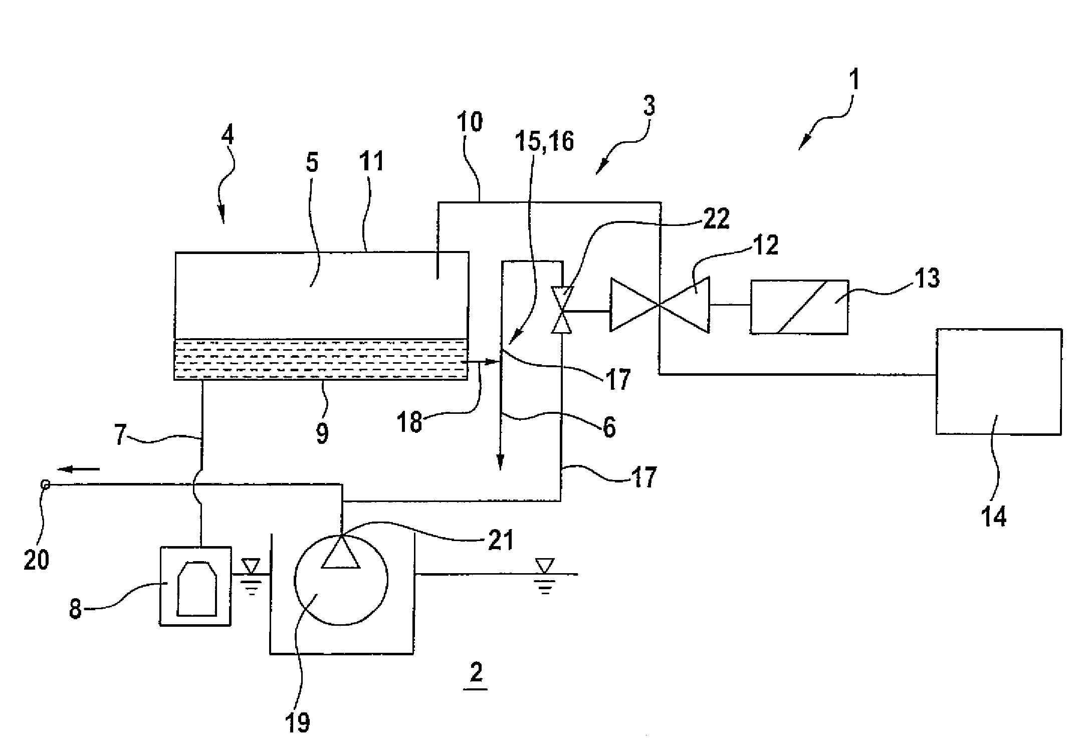
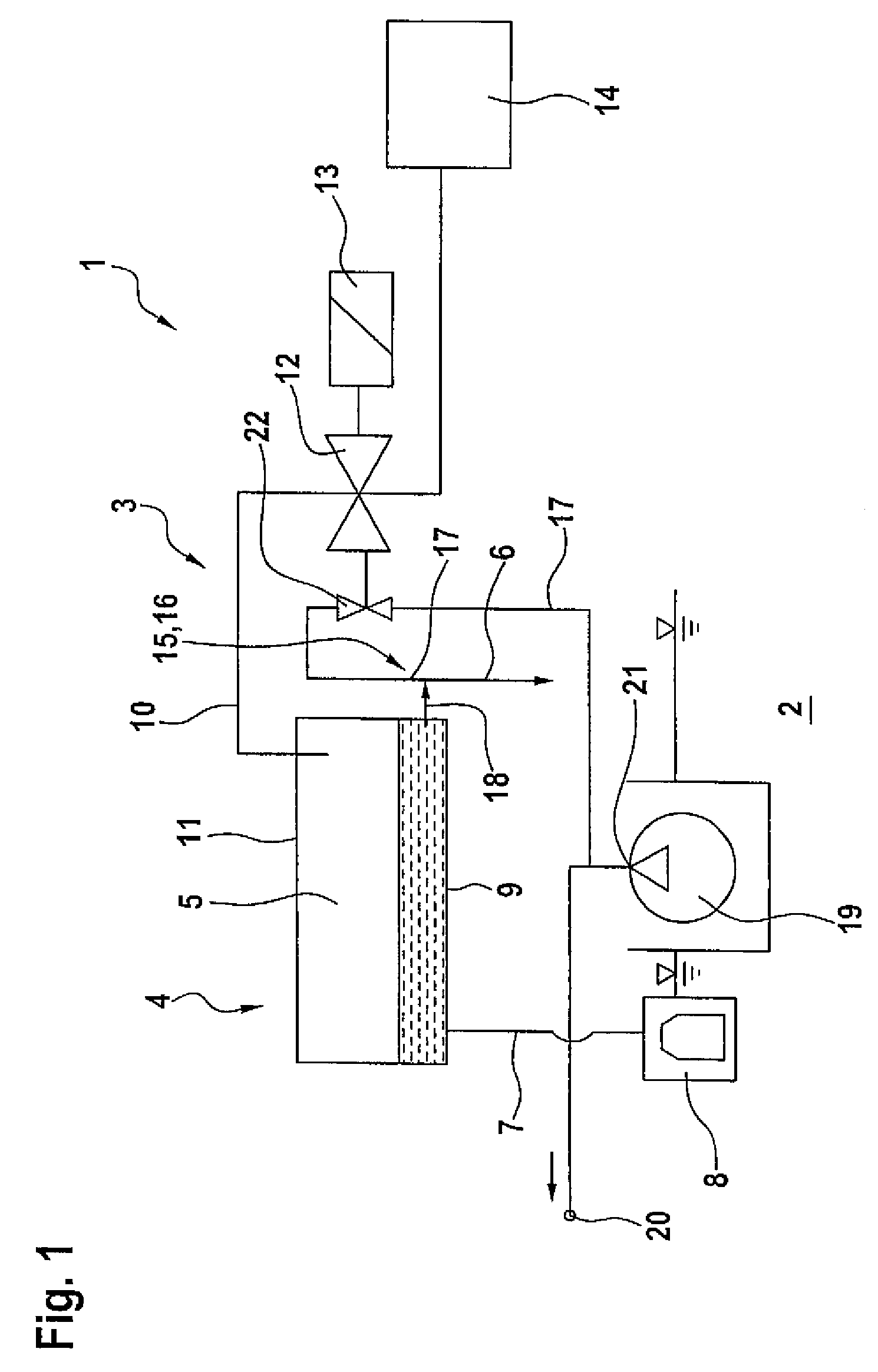
[0026]FIG. 1 shows a schematic representation of a fuel system 1. The fuel system 1 is for example part of a motor vehicle or a drive system respectively of the motor vehicle. The fuel system 1 has a fuel tank 2 and a ventilation device 3 for ventilating the fuel tank. The ventilation device has a separation device 4 with a temporary accumulator 5. The separation device 4 serves for separating liquid fuel from a mixture of liquid and gaseous fuel. The separated liquid fuel is subsequently present in the temporary accumulator 5 and can for example be conducted back into the fuel tank 2 again through a return line 6. The return line 6 preferably has a valve, in particular a drainage valve or check valve. Also, instead of the return line 6 only the valve can be provided, in particular when the separation device 4 is located at least in part in the fuel tank 2, so that fuel which escapes from the temporary accumulator 5 directly reaches the fuel tank through the valve. The valve is conf...


PUM


Abstract

A fuel system, in particular of a motor vehicle, includes a fuel tank and a ventilation device for ventilating the fuel tank, wherein the ventilation device has at least one separation device which has a temporary accumulator for liquid fuel and a fuel delivery device which is configured as jet pump for delivering fuel out of the temporary accumulator. In an operating medium line of the jet pump a pressure reducing element or a pressure adjustment element is provided.

Description

CROSS-REFERENCES TO RELATED APPLICATIONS[0001]This application claims the priority of German Patent Application, Serial No. 10 2010 055 317.4, filed Dec. 21, 2010, pursuant to 35 U.S.C. 119(a)-(d).BACKGROUND OF THE INVENTION[0002]The invention relates to a fuel system, in particular of a motor vehicle, with a fuel tank and a ventilation device for ventilating the fuel tank, wherein the ventilation device has at least one separation device which has a temporary accumulator for liquid fuel and a fuel delivery device which is configured as jet pump for delivering fuel out of the temporary accumulator.[0003]Fuel systems of the aforementioned type are known from the state of the art. They are assigned for example to a motor vehicle or a drive system of the motor vehicle. The drive system includes in particular at least one internal combustion engine and is for example configured as hybrid drive system, i.e. it includes the internal combustion engine as well as at least one electrical mac...

Claims


Application Information

Patent Timeline
IPC IPC(8): F02M33/08F02M33/02B60K15/035
CPCB60K15/035F02M33/08F02M33/02
Inventor HAGEN, HARALD
Owner AUDI AG
Why Eureka
Try Eureka