Shock absorber with increasing damping force

a technology of shock absorber and damping force, which is applied in the direction of vibration damper, spring/damper, spring, etc., can solve the problems of increased force per unit time, increased vehicle handling difficulty, and rapid changes in the distribution of adhesion between the road surface and the different wheels

Active Publication Date: 2015-02-17
OHLINS
View PDF15 Cites 14 Cited by
  • Summary
  • Abstract
  • Description
  • Claims
  • Application Information

AI Technical Summary

Benefits of technology

[0010]The present invention is intended to solve the problem of creating a gentle retarding of movement near the limit position of a shock absorber movement, which will prevent bottoming in the shock absorbing device, the gentle braking creating the prerequisites for a comfortable vehicle that also is predictable for the driver.
[0018]Moreover, the leakage flow past the piston has been minimized, which is to say the flow between the damping piston and the inner surface of the restricting space varies less as a function of the pressure. A minimal leakage flow is made possible in that the damping piston is designed to move in a radial direction in relation to the damping piston holder. A modulation of the restricting space is then possible without the need for a large difference between the outside diameter of the damping piston and the inner surface of the restricting space.
[0019]In order to allow a certain radial movement of the separating piston it is moreover not fully locked in an axial direction. This means that the tensioning, which varies as a function of the position of the damping piston relative to the device holding it, is influenced by any axial movement. Tensioning is made possible by the geometric design of the first flow limiter. The flow limiter is held between an outer damping piston surface and an inner damping piston surface, which are axially offset in relation to one another. The maximum counter-force for opening the first flow limiter is required when the flow limiter is under maximum tension. Maximum tensioning is obtained when the axial movement of the damping piston towards the main piston reaches its maximum. The flow limiter then bears against both the inner damping piston surface and the outer damping piston surface. The lower the velocity of the piston rod, the lower the impinging flow through the damping piston and hence also the lower the pressure drop over the damping piston, which is to say the axial movement of the damping piston towards the main piston is reduced.
[0020]The design with a large surface for the pressure to act upon in order to create the tensioning means that the tensioning can be achieved even in the event of small pressure drops over the damping piston, which is to say the tensioning is kept constant down to very low velocities. Since the velocity is usually greatest just when the damping piston has reached full engagement in the cup-shaped restricting space, the tensioning and the flow through the first flow limiter also reach a maximum at this point, which is to say the force acting on the first flow limiter is then greatest. Because the design of the flow limiter contributes to a damping piston that gives a slight increase in the pressure drop as the flow increases, the counter-force is reliably maintained even as the velocity and hence also the flow diminish. When the velocity then falls as the damping piston approaches its limit position, the counter-force also diminishes.
[0022]This design means that the damping piston is moveable in an axial and in a radial direction in relation to the piston rod. A modulation of the restricting space is therefore possible without the damping piston catching or without the need for a large amount of play between the damping piston and the inside diameter of the restricting space.

Problems solved by technology

It has proved a problem, in a shock absorber with this type of progressive damping, to create a gentle slowing of the damping movement in the limit position.
A relatively progressive damping characteristic is most often created, which creates a force that increases with velocity, which leads to large increases in the force per unit time when the second piston comes into engagement at a high velocity.
This behavior can be a problem for a driver of the vehicle, because the slowing may be perceived as jerky.
Rapid changes in the force between the wheel and the road surface risks leading to rapid changes in the distribution of the adhesion between the road surface and the different wheels.
This makes handling of the vehicle more difficult, since it becomes less predictable.
EP0565832 also illustrates a third problem of the known technology, which is the problem of creating a function that will afford a fully controllable slowing of the damping movement without the second piston at the same time contributing to a geometrically over-defined system, which may become locked or require extremely precise tolerances.

Method used


Image

  • Shock absorber with increasing damping force
  • Shock absorber with increasing damping force
  • Shock absorber with increasing damping force

Examples


Embodiment Construction

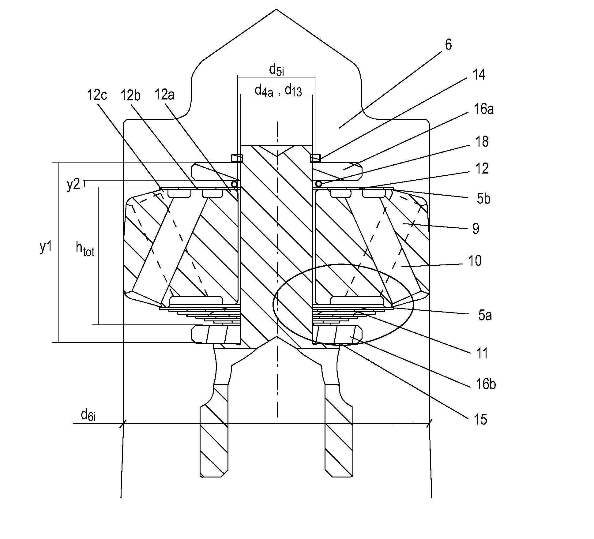
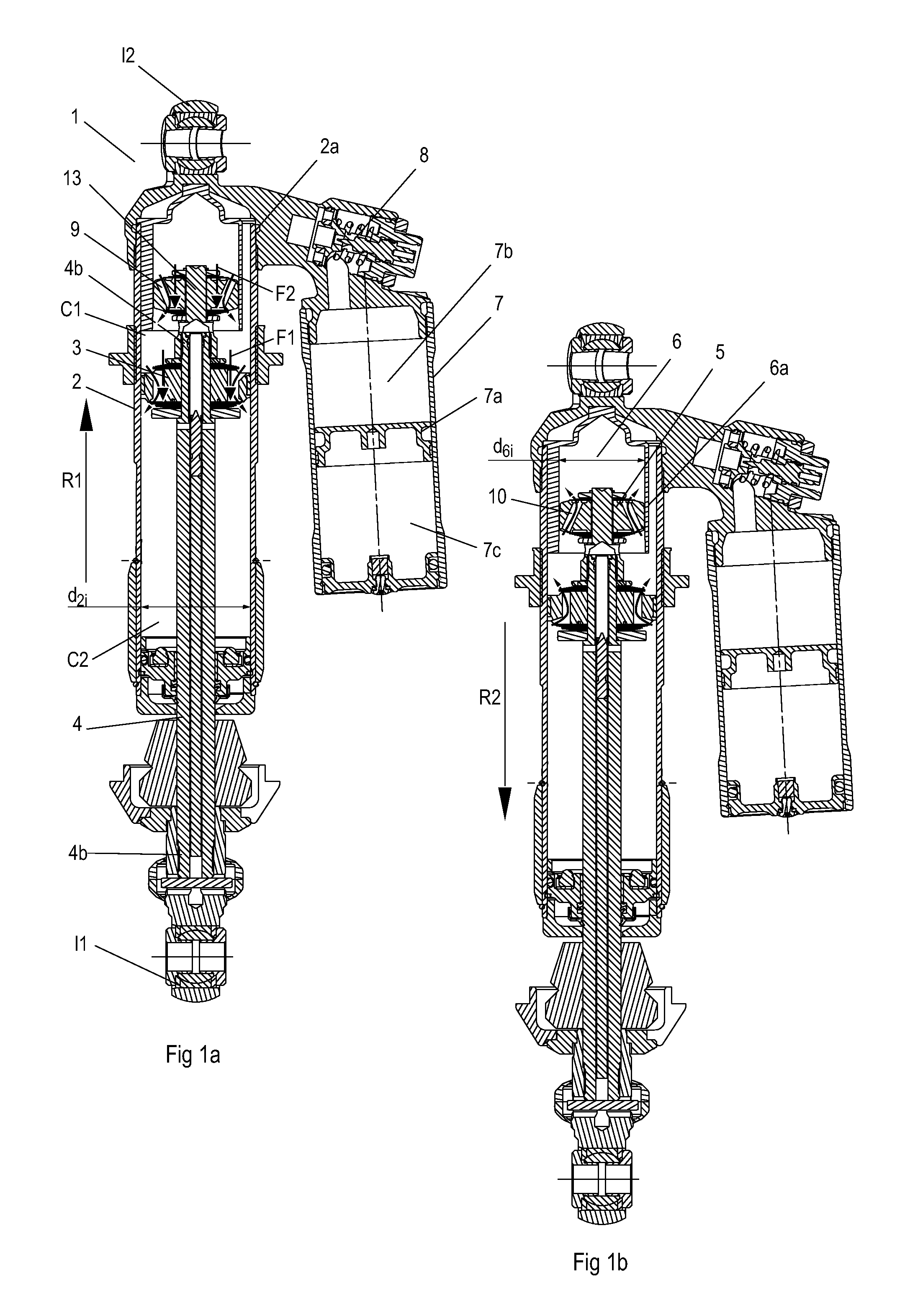
[0039]FIG. 1 shows a shock absorber 1 according to the invention. The shock absorber 1 in this embodiment comprises a damping cylinder 2 filled with damping medium M1 and divided into two damping chambers by a main piston 3 attached to a piston rod 4. The damping medium M1 is preferably hydraulic oil, which may contain associated additives of a type known in the art. Alternatively glycol and / or water may be used as fluid or damping medium. The two damping chambers may be referred to as a compression chamber C1 and a return chamber C2, since the main piston 3 moves axially in the damping cylinder 2 in a compression movement and a return movement in proportion to the movement of a vehicle wheel and chassis towards or away from one another in the directions R1, R2.

[0040]The second piston or damping piston 5, which has an outside diameter d5y, is seated on a damping piston holder part 13, located at an upper piston rod end 4a on the compression side of the main piston 3. The damping pis...


PUM


Abstract

A vehicle shock absorber generates an additional counter-force acting counter to the direction of movement near the limit position of movement. The shock absorber substantially comprises a damping medium-filled damping cylinder that is divided into two damping chambers by a main piston. The main piston is axially moveable relative to the damping cylinder and is attached to a piston rod. A second piston / damping piston that contains one or more first and second through-ducts is mounted to the piston rod. The ducts are defined by first and second flow-limiting devices such as multiple thin washers. The damping piston slides in a restricting space located in the damping cylinder. The restricting space has an inside diameter smaller than the inside diameter of the damping cylinder. The additional counter-force is substantially constant throughout the entire stroke in order to create gentle braking of the damping movement.

Description

CROSS-REFERENCE TO RELATED APPLICATIONS[0001]This application is a U.S. National Phase of International Application No. PCT / SE2008 / 051431, filed Dec. 10, 2008, which claims priority to Swedish Patent Application No. 0702798-0, which was filed on Dec. 14, 2007BACKGROUND OF THE INVENTION[0002]1. Field of the Invention[0003]The invention relates to a vehicle shock absorber comprising a damping medium-filled damping cylinder divided into two damping chambers, a compression chamber and a return chamber, by a main piston attached to a piston rod. The main piston moves axially in the damping cylinder in a compression and return movement. When the shock absorber reaches a certain compressed state, the movement is slowed by a function that increases the damping.[0004]2. Description of the Related Art[0005]This type of shock absorber is disclosed, for example, by EP0565832, GB998742 or the applicant's patent EP1006292B1, in which the compression movement is slowed by a second piston, herein r...

Claims


Application Information

Patent Timeline
Patent Type & Authority Patents(United States)
IPC IPC(8): F16F9/34F16F9/348F16F9/49F16F9/516
CPCF16F9/516F16F9/3485F16F9/49F16F9/3481F16F9/48
Inventor NYGREN, NILS GORANDANEK, MAGNUSJARL, JOHAN
Owner OHLINS
Why Eureka
Try Eureka