Vehicle driving force control device

a technology of driving force and control device, which is applied in the direction of motor/generator/converter stopper, dynamo-electric converter control, propulsion by batteries/cells, etc., can solve the problem of abnormal generation of brake force in the brake uni

Inactive Publication Date: 2015-02-17
MITSUBISHI MOTORS CORP
View PDF18 Cites 2 Cited by
  • Summary
  • Abstract
  • Description
  • Claims
  • Application Information

AI Technical Summary

Benefits of technology

[0006]It is therefore an object of the invention to provide a vehicle driving force control device in which a creep torque is reduced when the brake force is erroneously generated thereby eliminating the feeling as if a vehicle is pushed out.

Problems solved by technology

The brake unit may include a boosting unit that assists a stepping force for the brake pedal based on the detected stroke amount, and the monitoring unit may determine that the generation of the brake force in the brake unit is abnormal when performance of the boosting unit is abnormal.

Method used


Image

  • Vehicle driving force control device
  • Vehicle driving force control device
  • Vehicle driving force control device

Examples


first exemplary embodiment

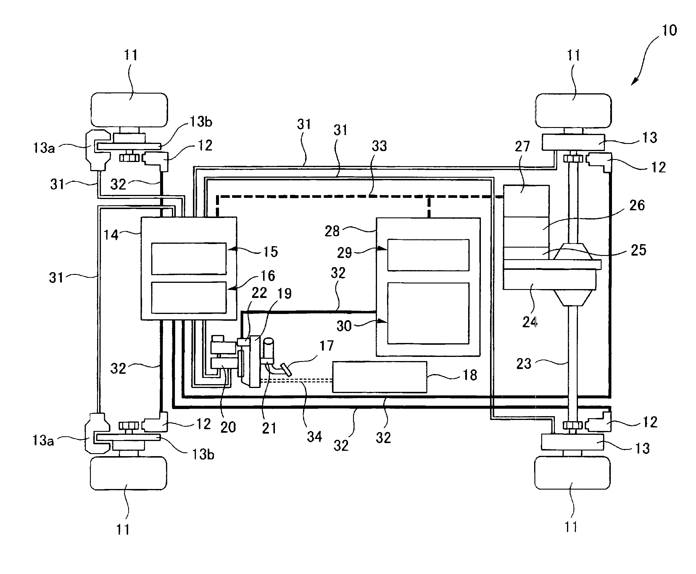
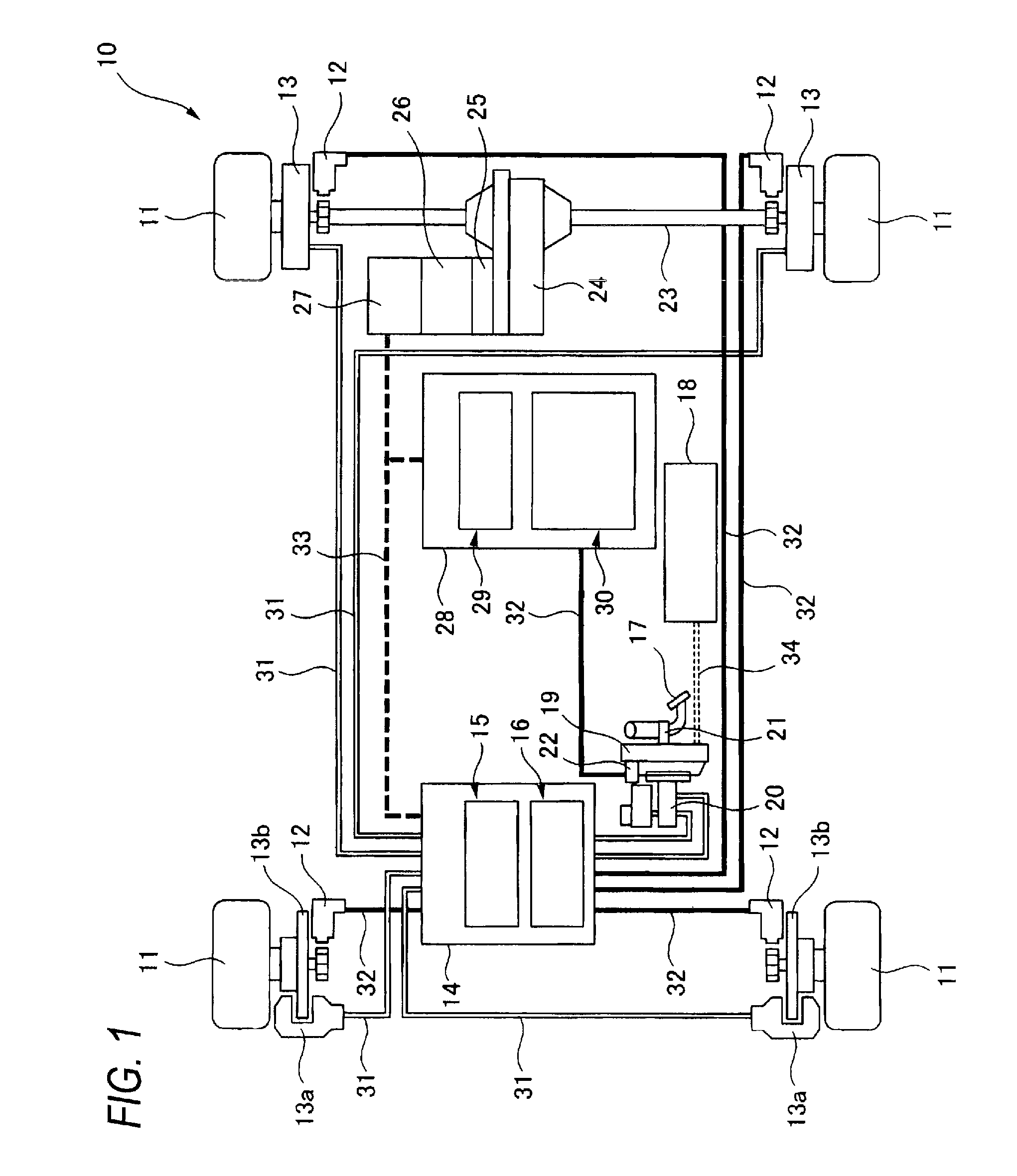
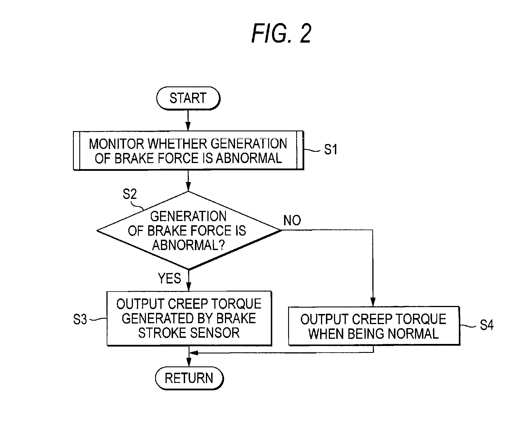
[0021]FIG. 1 is a schematic configuration diagram showing a vehicle driving force control device according to an exemplary embodiment of the present invention, and FIG. 2 is a flowchart explaining the control in the vehicle driving force control device shown in FIG. 1. FIGS. 3 to 5 are graphs to be used in the control shown in FIG. 2. FIG. 3 is a graph showing the relationship between a vehicle velocity and a creep torque, FIG. 4 is a graph showing the relationship between a stroke of a brake pedal and a reduction amount of a creep torque, and FIG. 5 is a graph showing the relationships between the stroke of the brake pedal and the creep torque when a brake is normal and abnormal. FIGS. 6 and 7 are flowcharts specifically explaining the monitoring whether brake force is abnormal in the control shown in FIG. 2. FIG. 6 is a flowchart explaining the monitoring whether the performance of a brake boosting device is abnormal, and FIG. 7 is a flowchart explaining the monitoring whether the...


PUM


Abstract

A vehicle driving force control device includes: a brake unit configured to generate a brake force of a vehicle; a stroke amount detecting unit configured to detect a stroke amount of a brake pedal of the vehicle; a monitoring unit configured to monitor whether generation of the brake force of the brake unit is abnormal; and a creep torque controlling unit configured to increase a reduction amount of a creep torque of the vehicle as the stroke amount increases, when the monitoring unit determines that the generation of the brake force in the brake unit is abnormal.

Description

BACKGROUND OF THE INVENTION[0001]The present invention relates to a vehicle driving force control device controlling a driving force of a vehicle.[0002]In an engine automatic transmission vehicle (hereinafter, referred to as an engine AT vehicle), even though an accelerator pedal is not operated, the vehicle can be slowly started (a creep phenomenon). Even in an electrically-driven vehicle such as an electric vehicle or a hybrid vehicle, the same control is performed. That is, even though the accelerator pedal is not operated, excitation current of a driving motor is controlled to control a creep torque, such that the vehicle can be slowly started.[0003]In a brake apparatus of a vehicle, a negative pressure type or a positive pressure type boosting device is provided assisting a force (a stepping force) for stepping a brake pedal, and a pressure of a brake fluid (hereinafter, referred to as a brake fluid pressure) is increased by using the boosting device to increase the brake force...

Claims


Application Information

Patent Timeline
Patent Type & Authority Patents(United States)
IPC IPC(8): F16H61/20B60L50/15B60L50/16B60W10/08B60W10/188B60W30/18B60W50/029B60W50/038
CPCB60W30/18063B60W10/08B60W50/029B60W50/038B60W10/188B60L11/123B60L11/14B60W2510/182B60W2540/12B60W2710/105Y02T10/7258B60W2710/083B60W2710/182Y02T10/7077Y02T10/6217Y02T10/70B60L50/61B60L50/16Y02T10/62Y02T10/72Y02T10/7072
Inventor OUE, TOSHIYAHAYASHIKAWA, KAZUFUMINAGURA, KATSUTOSHIIMOTO, KEISUKEMIYAMOTO, HIROAKIHATSUDA, YASUYUKISUGIMOTO, TAKANORIHATSUMI, NORIHIKO
Owner MITSUBISHI MOTORS CORP
Why Eureka
Try Eureka