
System and method for managing a powertrain in a vehicle

a technology for managing systems and powertrains, applied in the direction of braking systems, process and machine control, instruments, etc., can solve the problems of lack of fuel-saving benefits provided by wheel-end disconnects, low fuel economy, and often less-than-full-time systems. achieve the effect of minimizing the adverse impact of fuel economy

Active Publication Date: 2015-02-17
FORD GLOBAL TECH LLC
View PDF32 Cites 11 Cited by
  • Summary
  • Abstract
  • Description
  • Claims
  • Application Information

AI Technical Summary

Benefits of technology

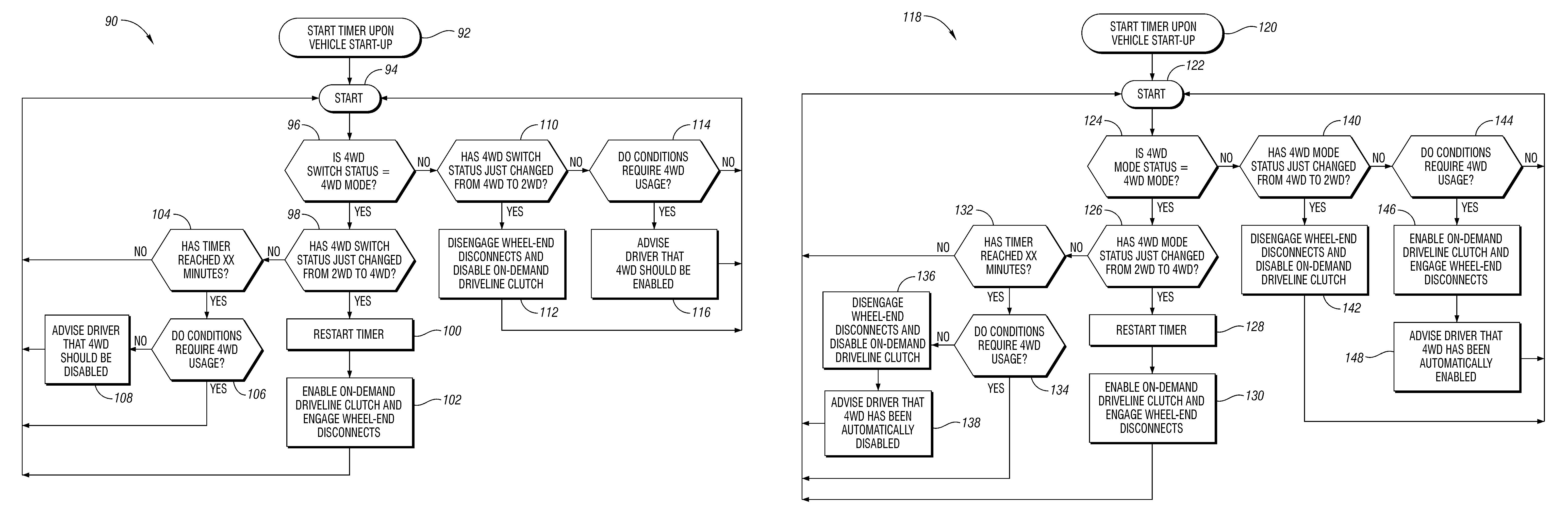
The present invention provides a system and method that utilizes an on-demand friction clutch and wheel-end disconnects to minimize the impact on fuel economy in four-wheel-drive systems. The vehicle has two pairs of drive wheels, and the first driving mode is a four-wheel-drive mode, and the second driving mode is a two-wheel-drive mode. The motor arrangement can be operated prior to connecting the clutch to bring the driveline components up to a synchronous speed with the drive wheels. The technical effects of the invention are to improve fuel economy and control the vehicle's performance in different driving modes.

Problems solved by technology

The absence of a center differential improves capability off-road, but precludes on-road usage because the lack of a center differential can cause problems with stability, handling and steering, and tire scrub.
A full-time system is often considered less capable than a part-time system in four-wheel-drive mode, because of its center differential.
While the on-demand system can make the vehicle capable in both on-road and off-road uses, it lacks the fuel-saving benefits provided by the wheel-end disconnects.
The rapid application and release of the friction clutch in the transfer case precludes the use of wheel-end disconnects, which cannot provide fast and frequent engagement and disengagement.

Method used


Image

  • System and method for managing a powertrain in a vehicle
  • System and method for managing a powertrain in a vehicle
  • System and method for managing a powertrain in a vehicle

Examples


Embodiment Construction

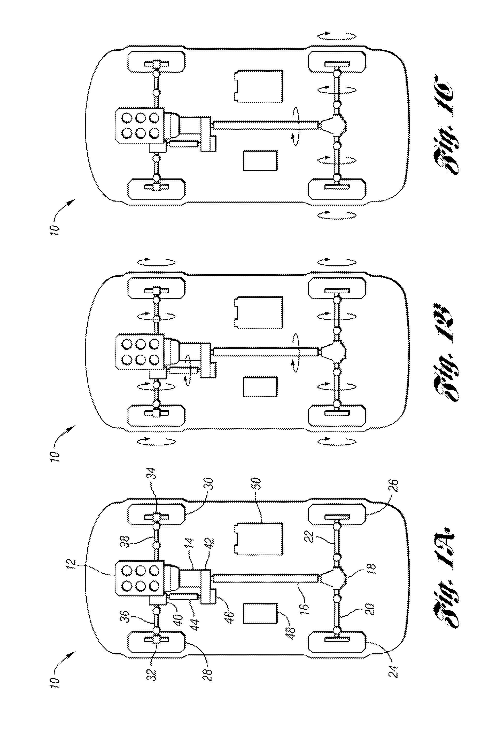
[0025]FIG. 1A shows a vehicle 10 that includes an engine 12, a transmission 14, and a rear drive shaft 16. The drive shaft 16 is connected to a rear differential 18, which has connected to it rear half-shafts 20, 22. The rear half-shafts 20, 22 are respectively connected to rear wheels 24, 26. As shown in FIG. 1A, the vehicle architecture is configured such that torque from the engine 12 is output through the transmission 14 to the drive shaft 16, and ultimately to the rear drive wheels 24, 26. In this configuration, the engine 12 is a “prime mover”, supplying the primary torque to drive the vehicle 10. The engine 12, transmission 14, drive shaft 16, differential 18, and rear half-shafts 20, 22 make up at least part of the vehicle powertrain.

[0026]The vehicle 10 also includes front drive wheels 28, 30, which are selectively connectable to and disconnectable from the powertrain by wheel-end disconnects 32, 34. When the disconnects 32, 34 are engaged, the wheels 28, 30 will rotate wit...


PUM


Abstract

A vehicle includes a first disconnect disposed between a prime mover of the vehicle and a certain one of the vehicle drive wheels. The first disconnect is operable to connect and disconnect the prime mover to and from the certain one of the drive wheels. A second disconnect is disposed between the powertrain and the certain one of the drive wheels, and is operable to connect and disconnect the certain one of the drive wheels to and from the powertrain when the first disconnect is engaged. A control system and method are configured to control operation of at least the first and second disconnects. Through selective control of the disconnects, the system can be automatically placed in a four-wheel-drive mode based on predetermined criteria, or the desirability of the four-wheel-drive mode can be indicated to the vehicle operator in a passive version of the control system and method.

Description

BACKGROUND OF THE INVENTION[0001]1. Field of the Invention[0002]The present invention relates to a system and method for managing a powertrain in a vehicle.[0003]2. Background Art[0004]Four-wheel-drive vehicles—conventional or hybrid electric vehicles (HEV's)—utilize various driveline components to deliver propulsion torque to the wheels of the vehicle. For example, when a part-time four-wheel-drive system is operated in the four-wheel-drive mode, torque is delivered continuously to both a primary axle and a secondary axle. While each axle contains a differential, the part-time system has no center differential—i.e., there is no differential between the two axles. This means that if one of the axle's wheels are on a zero-traction surface torque is still deliverable to the other axle's wheels.[0005]The absence of a center differential improves capability off-road, but precludes on-road usage because the lack of a center differential can cause problems with stability, handling and ste...

Claims


Application Information

Patent Timeline
Patent Type & Authority Patents(United States)
IPC IPC(8): G06F7/00G06F17/00G06F19/00B60K6/52B60K17/35B60K23/08B60W10/02B60W10/08B60W10/16B60W20/00
CPCB60K23/08B60K6/52B60K17/3515B60W10/02B60W10/08B60W10/16B60W20/00Y02T10/6265Y02T10/62B60K17/02B60K6/48B60K17/043B60W20/40B60W10/10
Inventor PERKINS, WILLIAM PAULGABOURY, SCOTT HOWARDDALEIDEN, STEVEN A.
Owner FORD GLOBAL TECH LLC
Learn More