Exhaust aftertreatment system and control method thereof

A technology of exhaust post-processing and control unit, which is applied in the direction of electronic control of exhaust treatment devices, exhaust treatment, exhaust devices, etc., and can solve the problems of enlarged flame, complex size and structure of burner, and difficult initial sliding control, etc. problem, to achieve the effect of reducing particulate matter

Active Publication Date: 2021-11-26
CERACOMB
View PDF29 Cites 0 Cited by
  • Summary
  • Abstract
  • Description
  • Claims
  • Application Information

AI Technical Summary

Problems solved by technology

Therefore, in the high-speed and high-load operation environment, the catalyst activity is extremely large, so the exhaust gas purification function will be performed normally, but in the case of low-speed high-load vehicles or frequent start and stop (stop&go) vehicles, due to the temperature of the exhaust gas Lower and it is difficult to make the aftertreatment system work properly, so the emission of harmful exhaust will increase
[0007] Therefore, various methods for raising the temperature of the exhaust gas have been developed and used. However, in order to use the burner to raise the temperature of the exhaust gas, the amount of fuel injection is large and the flame will also become large, so the size and structure of the burner will become complicated. , so that the operation and installation are also difficult, so the failure of the structural elements and the abnormal operation occur frequently
[0008] In addition, in the case of a large vehicle with a large exhaust flow rate, the control of the initial slip (slip) becomes difficult due to the large amount of fuel injection, and it is difficult to achieve stable restart efficiency

Method used


Image

  • Exhaust aftertreatment system and control method thereof
  • Exhaust aftertreatment system and control method thereof
  • Exhaust aftertreatment system and control method thereof

Examples


Embodiment Construction

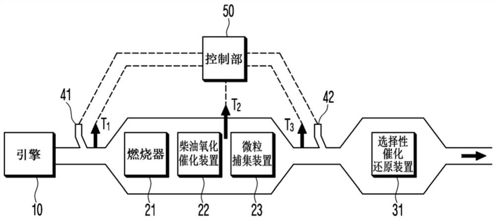
[0034] Hereinafter, the embodiments disclosed in this specification will be described in detail with reference to the drawings, and the same reference numerals will be assigned to the same or similar constituent elements regardless of the reference numerals, and repeated description thereof will be omitted. The suffixes "module" and "part" of the structural elements used in the following description are given or mixed in consideration of the simplicity of formulation of the description, and do not have mutually distinguishing meanings or functions. In addition, in describing the embodiments disclosed in this specification, if it is judged that the detailed description of related known technologies makes the gist of the embodiments disclosed in this specification unclear, the detailed description will be omitted. Moreover, the accompanying drawings are only used to easily understand the embodiments disclosed in this specification, and the technical ideas disclosed in this specif...


PUM


Abstract

The invention provides an exhaust gas post-treatment system. The exhaust gas post-treatment system is installed on the exhaust pipe of an internal combustion engine, and a particle trapping device and a selective catalytic reduction device are arranged sequentially from the upstream side. the upstream side of the trapping device for raising the temperature of the exhaust gas of the internal combustion engine; the hydrocarbon injector located on the upstream side of the particulate trapping device for injecting hydrocarbons into the exhaust gas; and the control part based on the first mode or the second mode for removing particulates controls the burner and the hydrocarbon injector, and when the temperature of the exhaust gas does not affect the operating temperature of the selective catalytic reduction device, the control part makes the burner perform operating to raise the temperature of the exhaust gas to the operating temperature of the selective catalytic reduction device, or according to the second mode, injecting hydrocarbons using the hydrocarbon injector while operating the burner to raise the temperature to the particulate removal temperature of the particulate trap device.

Description

[0001] This application claims priority from Korean Patent Application No. 10-2018-0128750 filed on October 26, 2018, the entire contents of which are incorporated herein by reference. technical field [0002] The present invention relates to an exhaust aftertreatment system and a control method thereof, and more particularly, to an exhaust aftertreatment system for purifying exhaust gas exhausted from an internal combustion engine mounted on a vehicle and a control method thereof. Background technique [0003] In general, there is an increasing demand for diesel engines that can realize high-efficiency and high-output operation in vehicles, ships, generators, and the like. This is due to the low price of diesel, which offers an advantage in terms of fuel economy or efficiency. [0004] When such a diesel engine is driven, nitrogen oxides (NOx) and particulate matter (PM, Particulate Matter), which cause air pollution, will be discharged together with the exhaust gas. Theref...

Claims


Application Information

Patent Timeline
Patent Type & Authority Patents(China)
IPC IPC(8): F01N9/00F01N3/025F01N3/20
CPCF01N3/025F01N3/0253F01N3/2033F01N3/208F01N9/00F01N9/002F01N2250/02F01N2570/10F01N2570/12F01N2570/14F01N2610/02Y02T10/40F01N3/2066F01N2240/14F01N2610/03F01N2610/1453F01N2900/1618
Inventor 李康洪李良鲁安启沅崔殷锡
Owner CERACOMB
Why Eureka
Try Eureka