
Automatic detection and adjustment of a pressure pod diaphragm

a technology of automatic detection and adjustment, which is applied in the direction of fluid pressure measurement, liquid/fluent solid measurement, instruments, etc., can solve the problems of constant incorrect pressure reading, inability to respond to pressure increases, and inability to monitor pressure of dialysis machine, etc., to achieve accurate and timely level adjustment

Active Publication Date: 2015-02-24
FRESENIUS MEDICAL CARE HLDG INC
View PDF24 Cites 22 Cited by
  • Summary
  • Abstract
  • Description
  • Claims
  • Application Information

AI Technical Summary

Benefits of technology

The patent text describes a new technology that automates the process of adjusting the level of a device, such as a camera or microphone. This technology improves the accuracy and timeliness of level adjustment compared to manual methods.

Problems solved by technology

When this happens, the pressure monitoring feature of the dialysis machine is no longer able to respond to pressure increases and records a constant incorrect pressure reading.

Method used


Image

  • Automatic detection and adjustment of a pressure pod diaphragm
  • Automatic detection and adjustment of a pressure pod diaphragm
  • Automatic detection and adjustment of a pressure pod diaphragm

Examples


Embodiment Construction

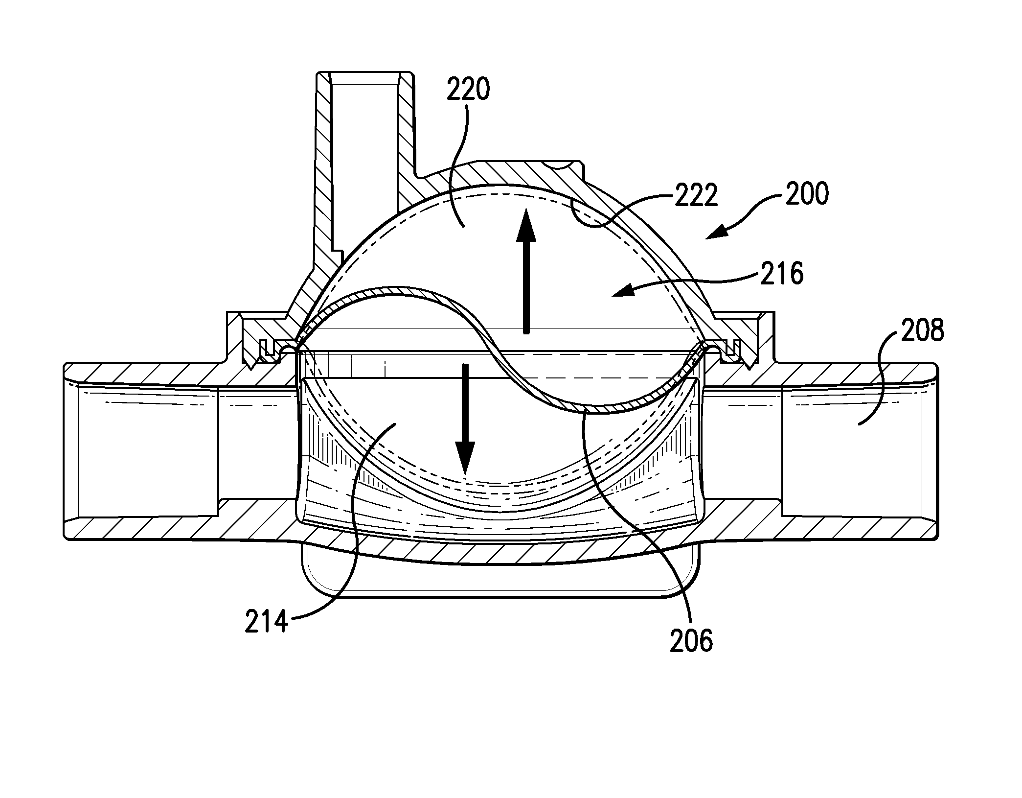
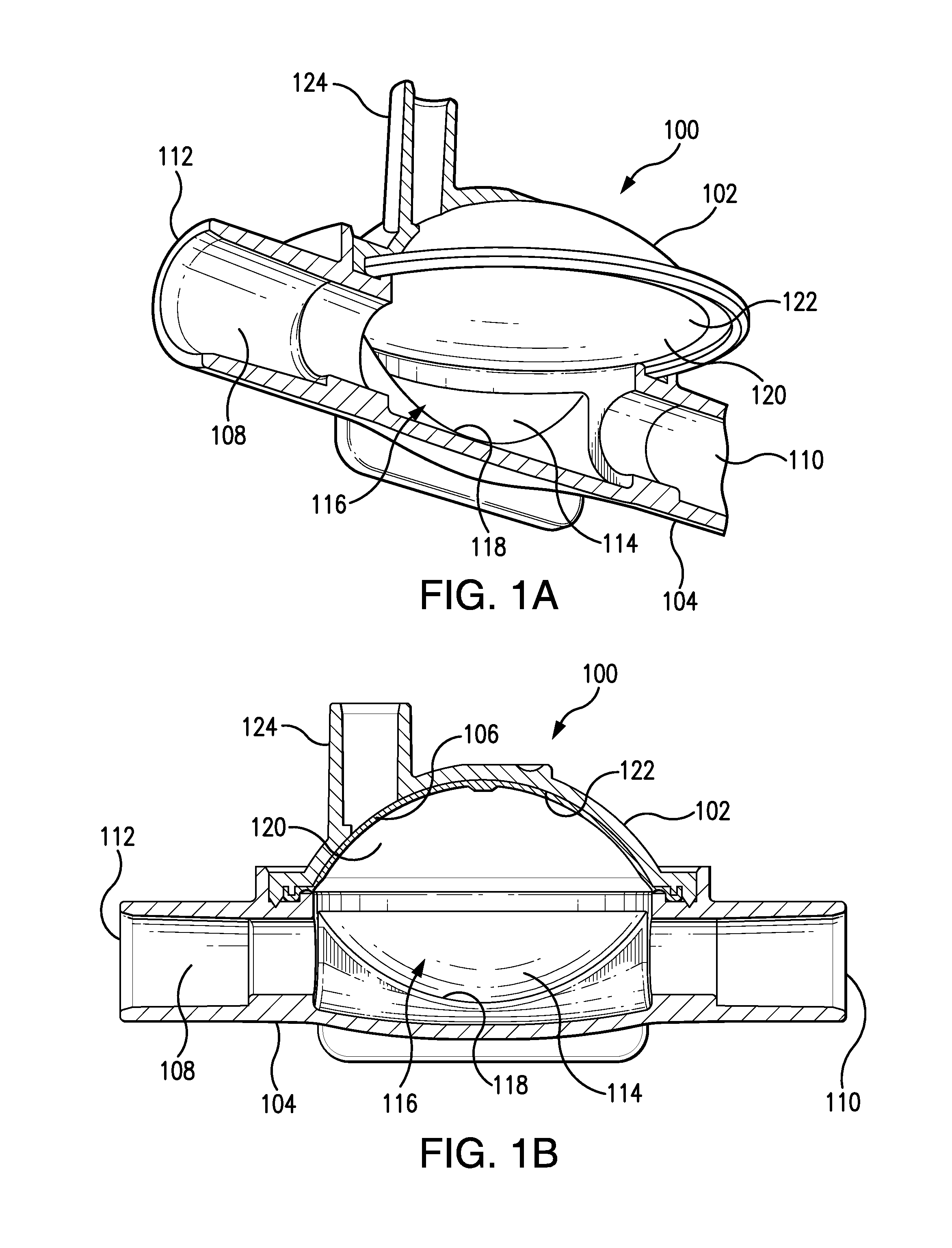
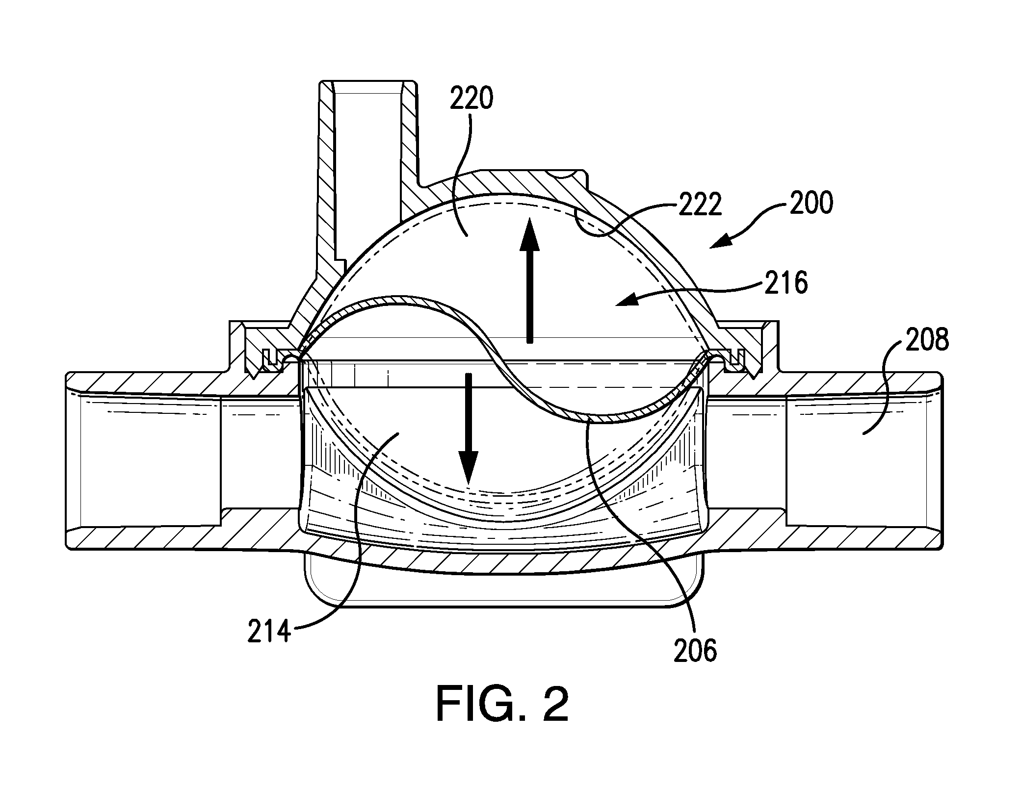
[0013]According to one or more embodiments of the present invention, a system is provided for controlling the position of a diaphragm in a diaphragm-containing pressure pod. The system can comprise a fluid pump, a pressure pod, a pressure sensor operatively connected to the pressure pod, and a controller configured to receive a pressure signal generated by the pressure sensor and to control a gas pressure inside the pressure pod based on the pressure signal received. Controlling the gas pressure inside the pressure pod can be used to position the diaphragm within the pressure pod so that can it can accurately generate pressure measurements.

[0014]The pressure pod can comprise any of a variety of pressure pods used to measure the pressure of a fluid flowing through the pod. The pressure pod can comprise of an interior, defining a flow-through fluid side and a gas side. The flow-through fluid side and the gas side can be separated from one another by the diaphragm. Exemplary pressure p...


PUM

PropertyMeasurementUnit
pressureaaaaaaaaaa
pressureaaaaaaaaaa
timeaaaaaaaaaa

Abstract

A system for controlling the position of a diaphragm in a diaphragm-containing pressure pod, is provided. The system can include a peristaltic pump, a pressure pod having a flow-through fluid side and a gas side that are separated by a diaphragm, and a pressure sensor operatively connected to the gas side. The pressure sensor is configured to sense pulses of pressure resulting from movement of the diaphragm and caused by the action of the peristaltic pump. A gas source and a valve can be in fluid communication with the gas side of the pressure pod and can be configured to provide gas to, or vent gas from, the gas side. A controller receives pressure signals from the pressure sensor and controls the valve in response, and in so doing, controls the position of the diaphragm. Methods for positioning the diaphragm are also included.

Description

FIELD OF THE INVENTION[0001]The present invention relates to a method and system for the automatic detection and adjustment of a pressure pod diaphragm used in an airless bloodline system.BACKGROUND OF THE INVENTION[0002]Airless bloodline systems have been implemented to include arterial and venous pressure monitor features known as “pressure pods.” These pods consist of a molded plastic feature integrated into the bloodline system to transmit pressure information from a blood side of the pod, across a thin diaphragm, to a measurement feature of the machine. Under certain operating conditions, for example, caused by operator errors, leaks, or damaged tubing, there is a possibility that the diaphragm can become pressed against the rigid inner surface or shell wall of the pressure pod, as shown in FIG. 2B. When this happens, the pressure monitoring feature of the dialysis machine is no longer able to respond to pressure increases and records a constant incorrect pressure reading. When...

Claims


Application Information

Patent Timeline
Patent Type & Authority Patents(United States)
IPC IPC(8): G01L7/00A61M1/36G01L7/08G01L27/00
CPCG01L7/088A61M1/3639G01L27/00A61M1/3641A61M2205/3331A61M2205/3379A61M2205/50A61M1/3607A61M1/34A61M2205/3344A61M1/3403A61M1/16
Inventor CRNKOVICH, MARTINTANENBAUM, LEEKOTSOS, MICHAEL EMMANUELWANG, FEIBROWN, ALEX
Owner FRESENIUS MEDICAL CARE HLDG INC
Learn More