
High frequency antenna formed on a compound surface

a compound surface and antenna technology, applied in the direction of sensing details, resistive material coating, computer peripheral equipment, etc., can solve the problems of minimizing the likelihood of unintended exchange, limiting the effective range of such rfid devices to a few centimeters, and the region near an rfid reader that provides enough rf energy to energize the rfid device in the wrist band can be quite small, so as to achieve effective reading

Active Publication Date: 2015-03-03
DISNEY ENTERPRISES INC
View PDF15 Cites 2 Cited by
  • Summary
  • Abstract
  • Description
  • Claims
  • Application Information

AI Technical Summary

Benefits of technology

[0006]The present disclosure addresses the above problems by providing a high frequency antenna formed on a compound surface that is formed into a non-planar shape. Advantageously, an RFID reader configured with such an antenna operates with an expanded region in which a short-range RFID device can be effectively read, while still requiring close proximity between the RFID device and the RFID reader for successful communication. In addition, the compound surface can be formed from a transparent or partially transparent material. Consequently, internal illumination in an RFID reader configured with such an antenna is readily visible, even when the compound surface conforms to a relatively large portion of the RFID reader housing.

Problems solved by technology

Due to the limited effective range of such an RFID device, explicit action on the part of the individual is required to initiate the transaction in question, thereby providing unambiguous intent and minimizing the likelihood of unintended exchanges.
However, because the effective range of such RFID devices is limited to a few centimeters, the region near an RFID reader that provides enough RF energy to energize the RFID device in the wrist band can be quite small.
Thus, unless an individual wearing such a wristband precisely positions the wristband in this small region where the RF cloud is strongest, read failures or read delays may result.
In applications in which large numbers of RFID wristbands must be read quickly, such delays are highly undesirable.

Method used


Image

  • High frequency antenna formed on a compound surface
  • High frequency antenna formed on a compound surface
  • High frequency antenna formed on a compound surface

Examples


Embodiment Construction

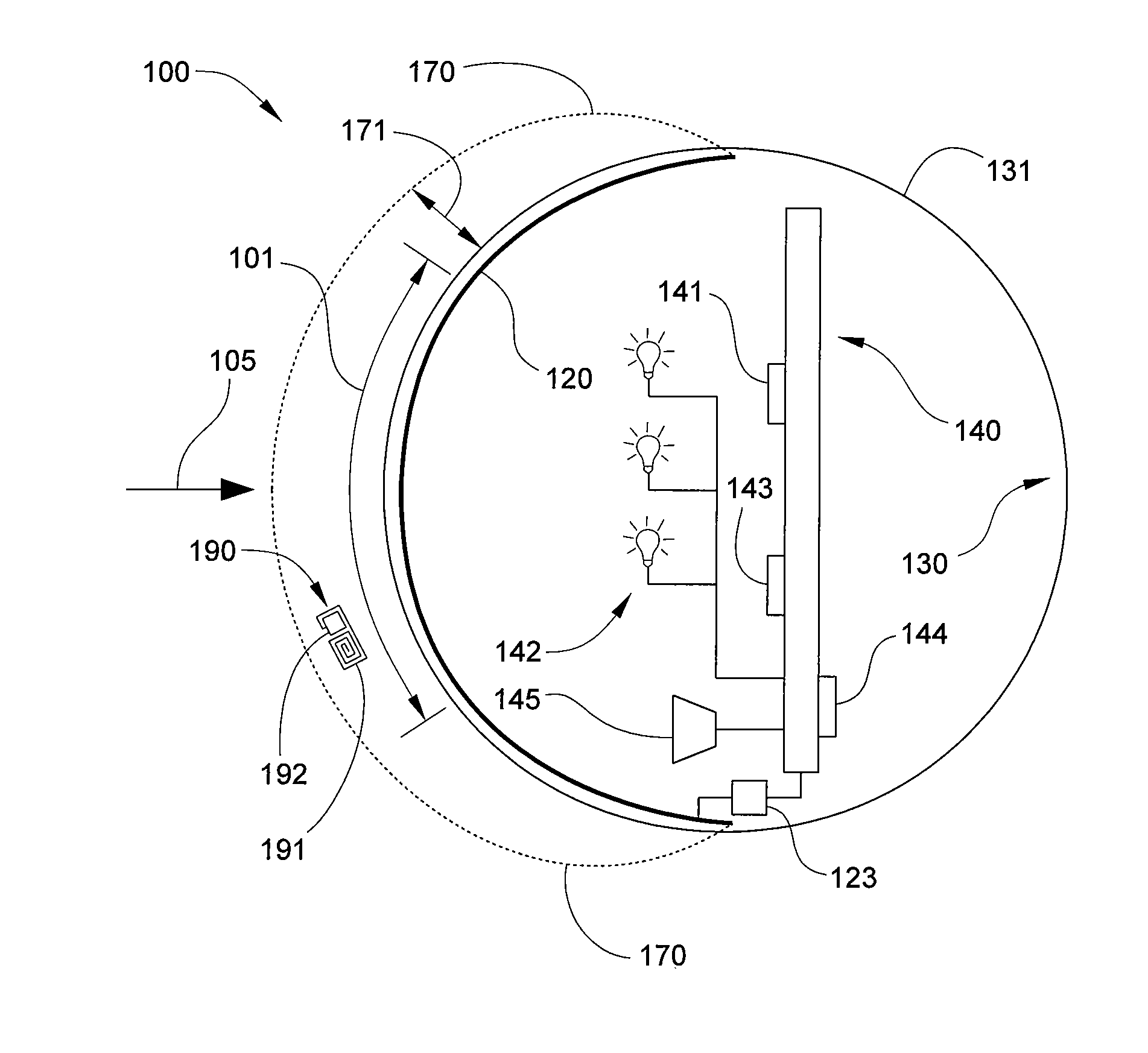
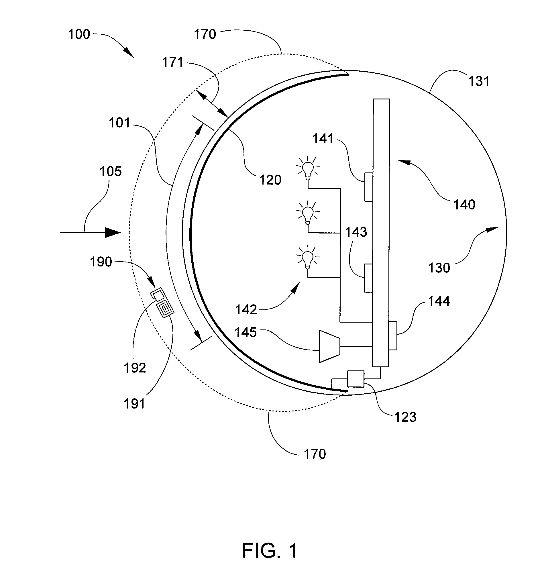
[0016]FIG. 1 illustrates a schematic cross-sectional side view of a radio-frequency identification (RFID) reader assembly 100 that includes a high frequency (HF) antenna 120 formed on a compound surface 131, according to one or more implementations of the disclosure. RFID reader assembly 100 includes HF antenna 120, a housing 130, and an electronics assembly 140, and is configured to read an HF RFID tag 190 via an associated antenna 191 when HF RFID tag 190 is positioned in an operating volume 170 of HF antenna 120. For example, HF RFID tag 190 may be embedded as an inlay in a wrist band worn by a user (not shown). When the user taps RFID reader assembly 100 on or near a designated target region 101 on compound surface 131, RFID reader assembly 100 queries HF RFID tag 190 and, based on the information provided by HF RFID tag 190, grants access to a restricted location, provides the user with a privileged service, and / or initiates a specific transaction with respect to the user.

[0017...


PUM

PropertyMeasurementUnit
radio-frequencyaaaaaaaaaa
frequencyaaaaaaaaaa
distanceaaaaaaaaaa

Abstract

An RFID reader includes an HF antenna formed on a compound, or three-dimensional, surface. With an HF antenna so configured, the RFID reader operates with an expanded region in which a short-range RFID device can be effectively read, while still requiring close proximity between the RFID device and the RFID reader for successful communication. Consequently, the physical security of information associated with the RFID device can be maintained while simultaneously enhancing the reliability of communications between the RFID device and an RFID reader. In addition, the HF antenna can be reliably and repeatably formed into a desired three-dimensional shape with a relatively simple two-step process.

Description

FIELD OF THE INVENTION[0001]The present disclosure relates generally to radio-frequency reader and antenna systems for identifying radio-frequency identification tags and, more specifically, to a high-frequency antenna formed on a compound surface.BACKGROUND OF THE INVENTIONDescription of the Related Art[0002]Radio-frequency identification (RFID) is a technology using radio waves to transfer data from an electronic tag, referred to as an RFID tag or RFID label, that is attached to an object. The data from the RFID tag is transferred to a reader, typically for the purpose of identifying and / or tracking the object to which the RFID tag is attached. One such RFID technology is short-range RFID or “tap technology,” which relies on high frequency (HF) radio waves (13.56 MHz, for example) for “near-field” communication between the reader and the RFID tag.[0003]The “near-field” of a transmitting antenna is a region in which there are strong inductive and capacitative effects from the curre...

Claims


Application Information

Patent Timeline
Patent Type & Authority Patents(United States)
IPC IPC(8): G06K7/00
CPCG06K7/01H01Q1/36H01Q1/1271H01Q1/2225H01Q1/38G06K7/10316
Inventor BRASHER, WILLIAM E.WORRAL, DAVIDWIEDEFELD, WILLIAM G.
Owner DISNEY ENTERPRISES INC
Learn More