Low electron temperature microwave surface-wave plasma (SWP) processing method and apparatus

a surface-wave plasma and low-electromagnetic technology, applied in the field of surface-wave plasma processing, can solve the problems of still suffering from the practical implementation of swp sources, and achieve the effects of enhancing plasma uniformity, reducing electron temperature, and high degree of ionization

Active Publication Date: 2015-03-03
UNIV HOUSTON SYST +1
View PDF25 Cites 22 Cited by
  • Summary
  • Abstract
  • Description
  • Claims
  • Application Information

AI Technical Summary

Benefits of technology

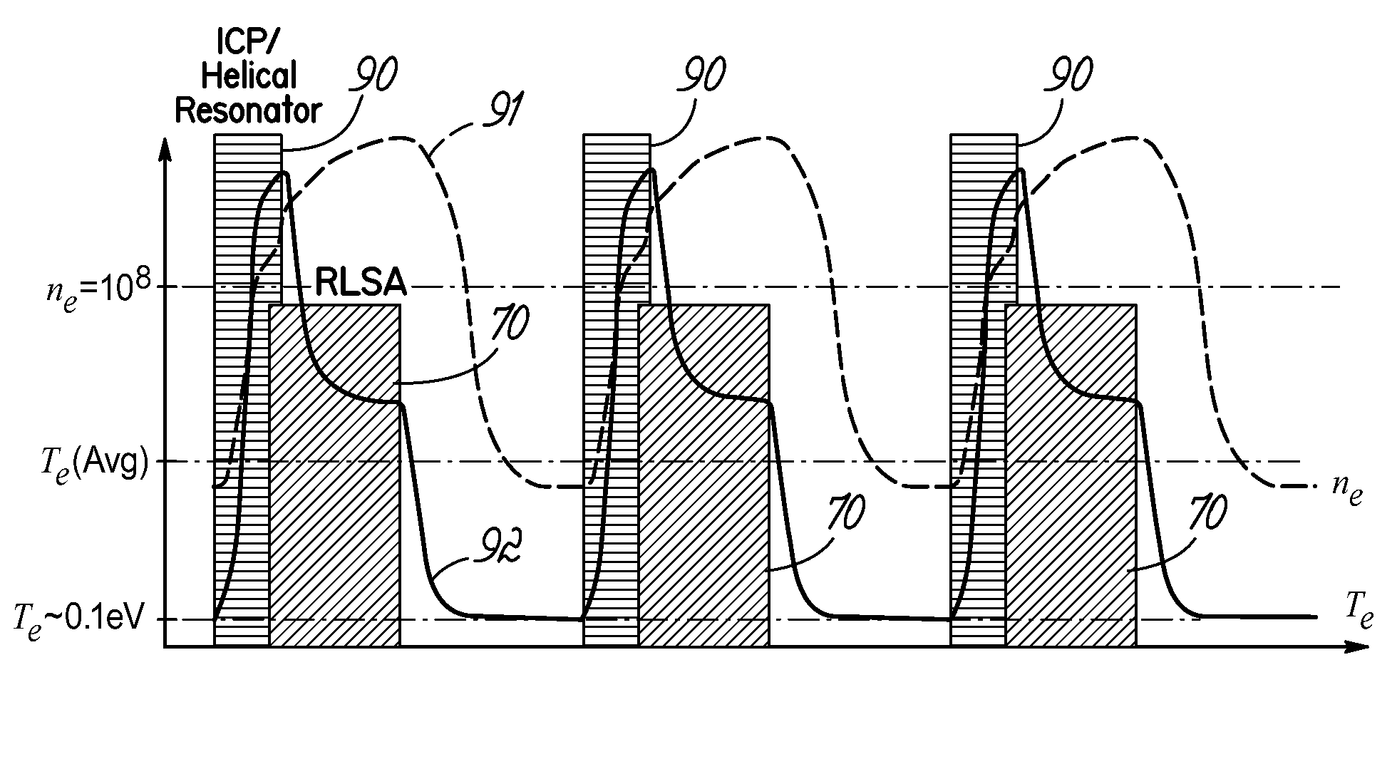
[0006]According to principles of the present invention, a surface wave plasma (SWP) source is provided that produces a high degree of ionization at substantially lower electron temperature than SWP sources of the prior art. According to further principles of the invention, the low electron temperature is provided with enhanced plasma uniformity.
[0008]In accordance with further principles of the present invention, in order to prevent impingement of the microwave energy onto the surface of the wafer when plasma density is low, such as between pulses of the microwave energy from the SWP, a secondary plasma source in the form of an ICP source, which can be, for example, a helical inductive source, a planar RF coil, or other inductively coupled source, is provided to produce a secondary plasma between the SWP source and the wafer that is opaque to microwave energy.
[0010]According to further principles of the invention, the ICP is combined with the SWP so as to introduce a ring-shaped distribution of energy to add an edge dense distribution of plasma to a generally chamber centric plasma produced by the SWP. As a result, improved plasma uniformity is provided. The relative energy delivered by the ICP and SWP sources provide a uniformity control parameter for the resulting plasma.

Problems solved by technology

However, the practical implementation of SWP sources still suffers from several deficiencies including, for example, plasma stability and uniformity, and electron temperature that is still higher than preferred.

Method used


Image

  • Low electron temperature microwave surface-wave plasma (SWP) processing method and apparatus
  • Low electron temperature microwave surface-wave plasma (SWP) processing method and apparatus
  • Low electron temperature microwave surface-wave plasma (SWP) processing method and apparatus

Examples


Embodiment Construction

[0022]A microwave plasma processing method and apparatus are disclosed in various embodiments. However, one skilled in the relevant art will recognize that the various embodiments may be practiced without one or more of the specific details, or with alternative methods, materials, or components. Well-known structures, materials, or operations are not shown or described in detail to avoid obscuring aspects of various embodiments of the invention.

[0023]Similarly, for purposes of explanation, specific numbers, materials, and configurations are set forth in order to provide a thorough understanding of the invention. Nevertheless, the invention may be practiced with alternative specific details. Furthermore, the various embodiments shown in the figures are illustrative representations and are not necessarily drawn to scale.

[0024]References throughout this specification to “one embodiment” or “an embodiment” or “certain embodiments” or variations thereof means that a particular feature, s...


PUM

PropertyMeasurementUnit
sizeaaaaaaaaaa
sizeaaaaaaaaaa
dielectric constantaaaaaaaaaa

Abstract

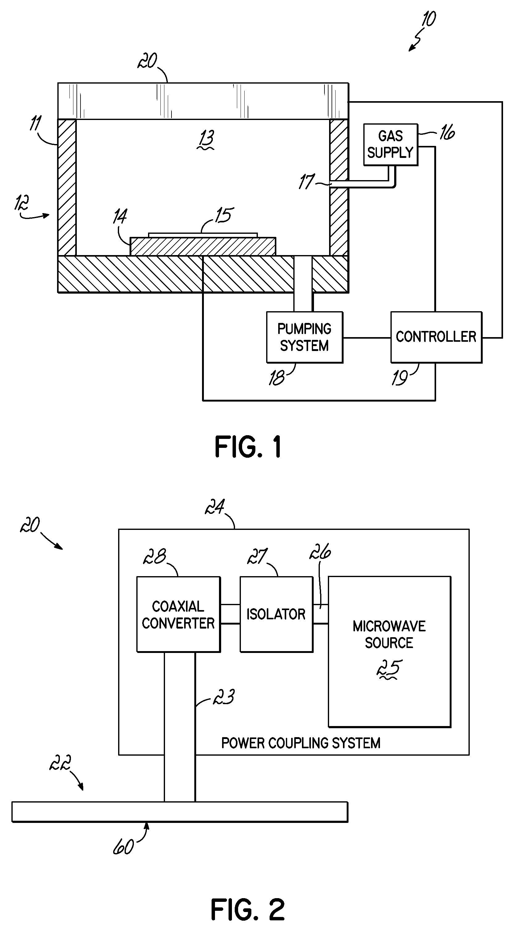
A surface wave plasma (SWP) source couples pulsed microwave (MW) energy into a processing chamber through, for example, a radial line slot antenna, to result in a low mean electron energy (Te). To prevent impingement of the microwave energy onto the surface of a substrate when plasma density is low between pulses, an ICP source, such as a helical inductive source, a planar RF coil, or other inductively coupled source, is provided between the SWP source and the substrate to produce plasma that is opaque to microwave energy. The ICP source can also be pulsed in synchronism with the pulsing of the MW plasma in phase with the ramping up of the MW pulses. The ICP also adds an edge dense distribution of plasma to a generally chamber centric MW plasma to improve plasma uniformity.

Description

FIELD OF THE INVENTION[0001]The invention relates to plasma processing with microwave (MW) plasmas, particularly surface wave plasmas (SWP), for example as produced with a radial line slot antenna, and more particularly, to a method and apparatus providing relatively low electron temperature and plasma uniformityBACKGROUND OF THE INVENTION[0002]Typically, during semiconductor processing, a plasma etch process, for example a dry plasma etch process, is utilized to remove or etch material along fine lines or within vias or contacts patterned on a semiconductor substrate. The plasma etch process generally involves positioning a semiconductor substrate with an overlying patterned, protective layer, for example a photoresist layer, into a processing chamber and etching exposed areas of the substrate through the pattern.[0003]Once the substrate is positioned within the chamber, it is etched by introducing an ionizable, dissociative gas mixture into the chamber at a pre-specified flow rate...

Claims


Application Information

Patent Timeline
Patent Type & Authority Patents(United States)
IPC IPC(8): H01L21/302H01L21/461B44C1/22C03C15/00C03C25/68C23F1/00
CPCC23C16/511H05H1/46H01J37/32192H01J37/32293H05H1/4615H05H1/463
Inventor ZHAO, JIANPINGCHEN, LEEDONNELLY, VINCENT M.ECONOMOU, DEMETRE J.FUNK, MERRITTSUNDARARAJAN, RADHA
Owner UNIV HOUSTON SYST
Why Eureka
Try Eureka