
Linear actuator

a technology of linear actuators and actuators, applied in the direction of arms, manufacturing tools, gears, etc., can solve the problems of large ground footprint, inability to adapt well, and high cost of manufacture and maintenance, and achieve good resistance over time.

Active Publication Date: 2015-03-10
THALES SA
View PDF19 Cites 4 Cited by
  • Summary
  • Abstract
  • Description
  • Claims
  • Application Information

AI Technical Summary

Benefits of technology

[0019]In another embodiment, the first elastic cable can be fixed to a first lateral part of the mobile plate. The linear actuator may comprise at least one second elastic cable fixed by one of its ends to a second lateral part of the mobile plate, and fixed by its other end to the support. The second elastic cable is engaged in a second pulley fixed to the support. The first and second elastic cables, the first pulley and the second pulley are arranged so as to obtain a stable balance for the linear actuator.
[0023]In a particularly advantageous embodiment, the first cable and the second cable can have a different stiffness.
[0027]The main advantages of the invention are notably that it is reliable and provides good resistance over time.

Problems solved by technology

One of the problems associated with the use of electric motion actuators relates to having to take into account the static forces linked to the load being displaced and the dynamic forces linked to the weight and the inertia of the load being displaced.
The pneumatic and hydraulic compensation solutions have the following main defects:they have a large ground footprint;they are expensive to manufacture and maintain;they are subject to pressure equipment usage standards which are highly restrictive;they do not adapt well according to the variations of the static force applied to the actuator because the compensation force is relatively constant.
Furthermore, the pneumatic compensation systems take a relatively long time to start up, adding an additional constraint to the use of the simulator.

Method used


Image

  • Linear actuator
  • Linear actuator
  • Linear actuator

Examples


Embodiment Construction

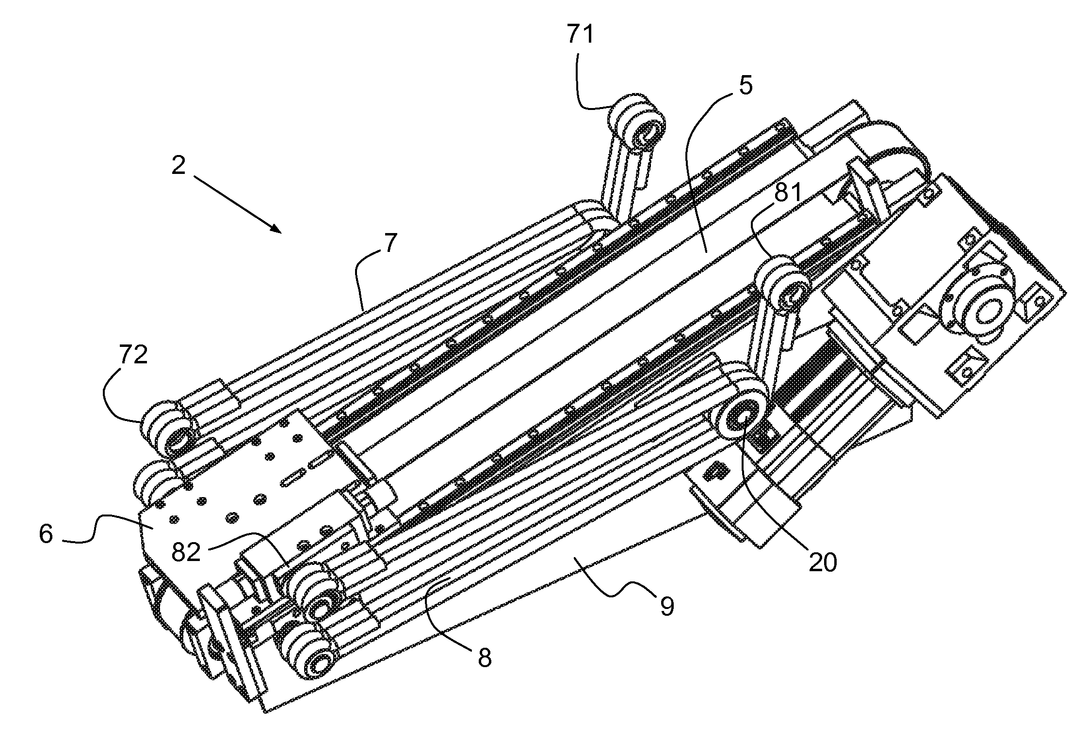
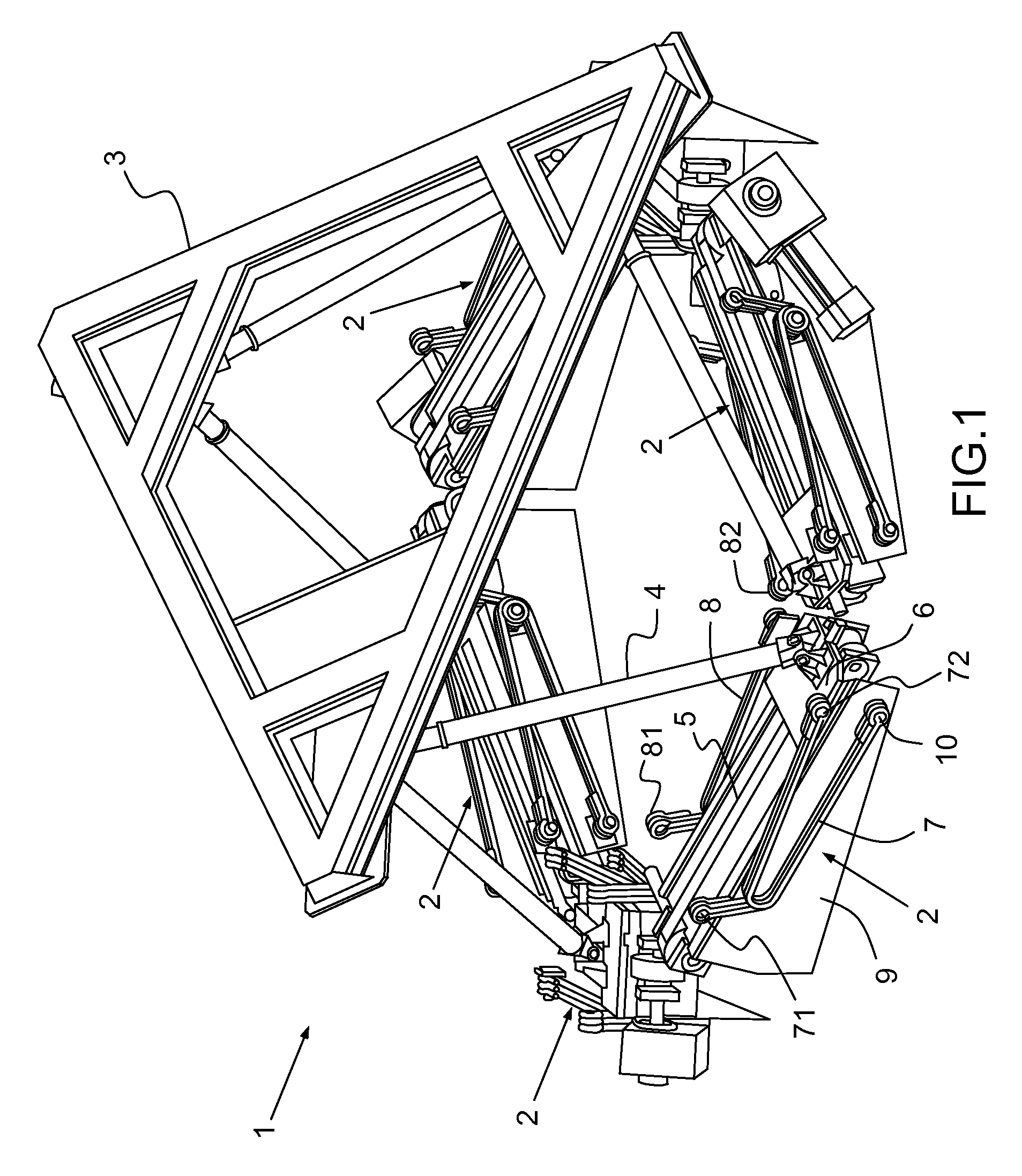
[0034]FIG. 1 represents a hexapod positioner 1 comprising at least one actuator 2 according to the invention. The hexapod positioner 1 can set a mobile platform 3 in motion. The hexapod positioner 1 can be produced according to the Stewart platform concept allowing for movement of the mobile platform 3 according to six degrees of freedom. Three degrees of freedom in translation, three degrees of freedom in rotation according to pitch, roll and yaw angles, otherwise called Euler angles. The Stewart platforms are notably used to produce simulators after a design by K. Cappel. The Stewart platforms form part of the family of parallel robots.

[0035]The hexapod positioner 1 notably comprises six actuators. The load of the platform 3 is distributed over the six actuators of the hexapod positioner 1. For example, the six actuators may be actuators 2 according to the invention. In another exemplary embodiment, a hexapod positioner may comprise at least one actuator 2 according to the inventi...


PUM


Abstract

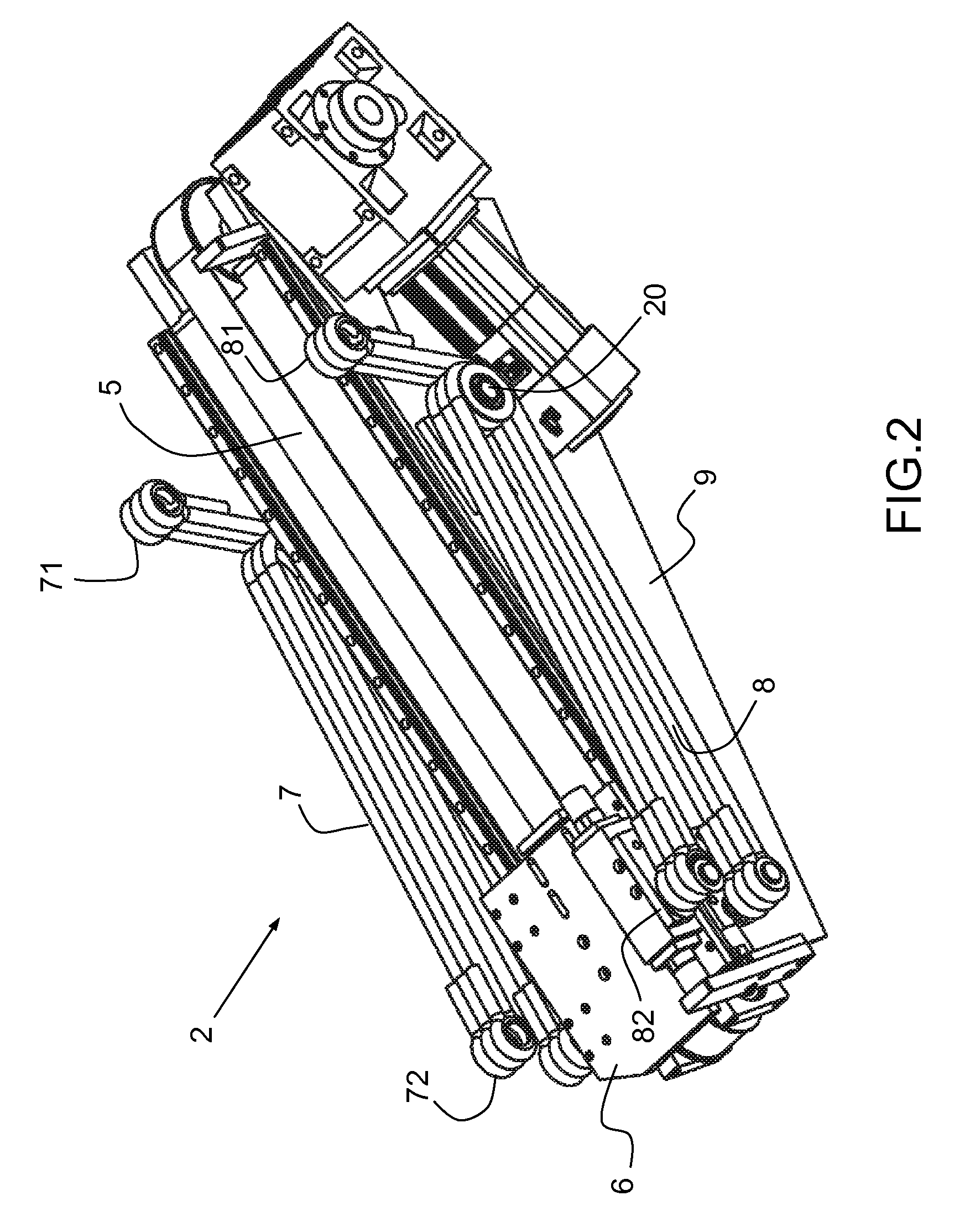
A linear actuator suitable for mobilizing a load comprises: a leg linked to the load by one of its ends with a ball joint with three degrees of freedom in rotation; a plate that is mobile in translation along an axis belonging to a plane of a support of the actuator, said mobile plate being mechanically linked to the leg by its other end. The linear actuator also comprises at least one first elastic cable, fixed by one of its ends to the mobile plate, and fixed by its other end to the support, being engaged in a first pulley fixed to the support. The actuator can notably be used to mobilize a simulation platform mounted on a hexapod.

Description

CROSS-REFERENCE TO RELATED APPLICATION[0001]This application claims priority to foreign French patent application No. FR 1102156, filed on Jul. 8, 2011, the disclosure of which is incorporated by reference in its entirety.FIELD OF THE INVENTION[0002]The present invention relates to a linear actuator, notably used to mobilize a simulation platform mounted on a hexapod.BACKGROUND[0003]The invention relates to the field of motion system actuators used for example for: flight and vehicle driving simulators. The simulators for which the invention applies are simulators comprising, for example, a real piloting or driving booth. The use of a real booth means that the simulator has a weight and a size that are both significant.[0004]In order to maintain the simulators, reduce the cost of the infrastructures in which the simulators are placed, and the cost of the energy to be supplied to mobilize a simulator, it is increasingly commonplace to use electric motion actuators instead of hydrauli...

Claims


Application Information

Patent Timeline
Patent Type & Authority Patents(United States)
IPC IPC(8): F16H21/44B25J9/10B25J17/02
CPCF16H21/44B25J17/0266B25J9/104Y10S901/22Y10T74/18968Y10T74/20305Y10T74/20317Y10T74/20323
Inventor DUPLOUY, OLIVIER
Owner THALES SA
Learn More