Shutter glasses and related 3D display system

a display system and shutter glasses technology, applied in optics, instruments, electrical equipment, etc., can solve the problems of 3d motion blur and luminance insufficiency of 3d image, increase the manufacturing cost of lcd panels, and consume more power, so as to reduce 3d crosstalk and shorten the response time of shutter glasses, the effect of reducing power consumption

Inactive Publication Date: 2015-03-10
TCL CHINA STAR OPTOELECTRONICS TECH CO LTD
View PDF8 Cites 1 Cited by
  • Summary
  • Abstract
  • Description
  • Claims
  • Application Information

AI Technical Summary

Benefits of technology

[0008]It is therefore one of the primary objectives of the present invention to provide a shutter glasses and a 3D display system, to reduce power consumption and 3D crosstalk.
[0029]In contrast to the related art, the present invention installs stacked normally-white LCD panel and normally-black LCD panel in the shutter glasses. Furthermore, the present invention installs an optical compensation film between the first polarizer and the liquid crystal layer of the normally-black LCD panel or / and between the second polarizer and the liquid crystal layer of the normally-black LCD panel. In this way, the present invention is able to compensate for the dispersion when the normally-black LCD panel is in a dark mode such that the 3D crosstalk is reduced. Moreover, the present invention installed the normally-white LCD panel and the normally-black LCD panel having different thicknesses. This makes the response time of the shutter glasses respectively equal to the voltage rising time of the normally-white LCD panel and the normally-black LCD panel. Therefore, the response time of the shutter glasses is shorten such that a purpose of lower the power consumption can be achieved.

Problems solved by technology

Therefore, this often introduces a 3D motion blur and a luminance insufficiency of the 3D image.
Unfortunately, these two solutions consume more power and raise the manufacturing cost of the LCD panel.

Method used


Image

  • Shutter glasses and related 3D display system
  • Shutter glasses and related 3D display system
  • Shutter glasses and related 3D display system

Examples


Embodiment Construction

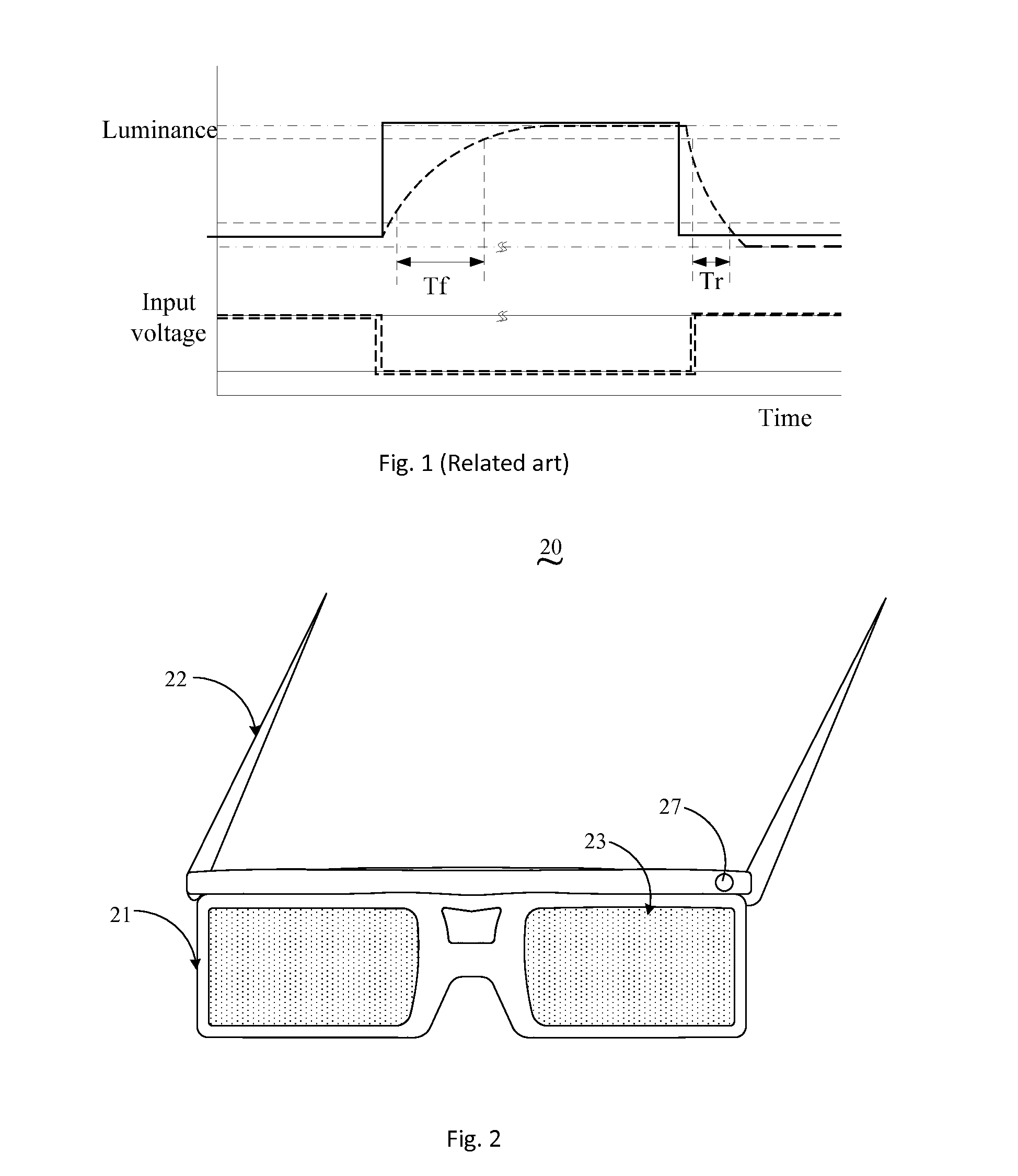
[0040]Please refer to FIG. 2, which is a diagram showing a structure of shutter glasses according to a first embodiment of the present invention. As shown in FIG. 2, the shutter glasses 20 comprise a frame 21, legs 22, LCD panels 23, and a driving circuit 27. The legs 22 are used to support the frame 21. The frame 21 is used to support the LCD panels 23, which are utilized as lens. The driving circuit 27 is installed on the legs and is used to generate a driving signal to drive the LCD panels 23. Furthermore, the driving signal is optimized as a square wave signal.

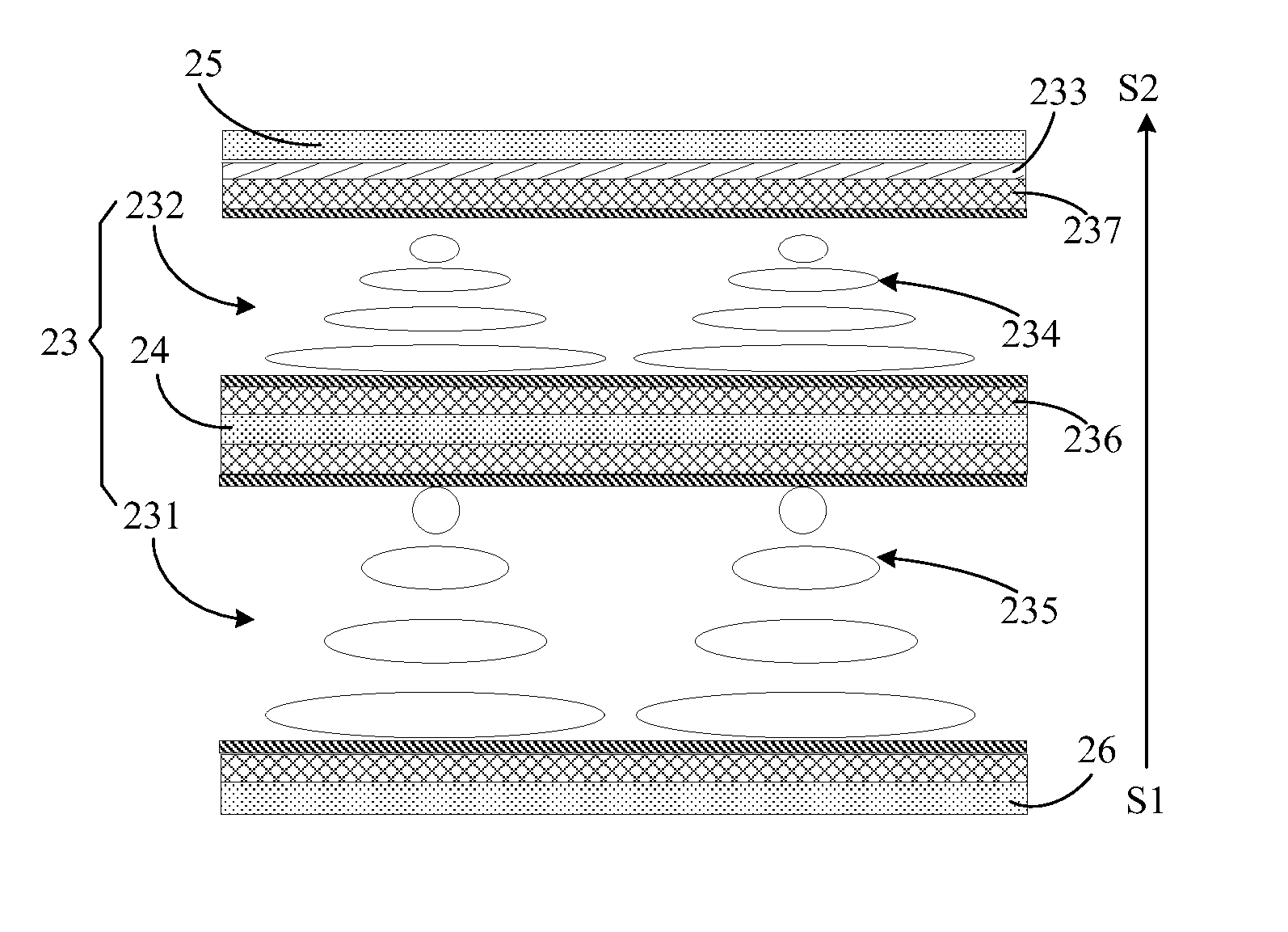
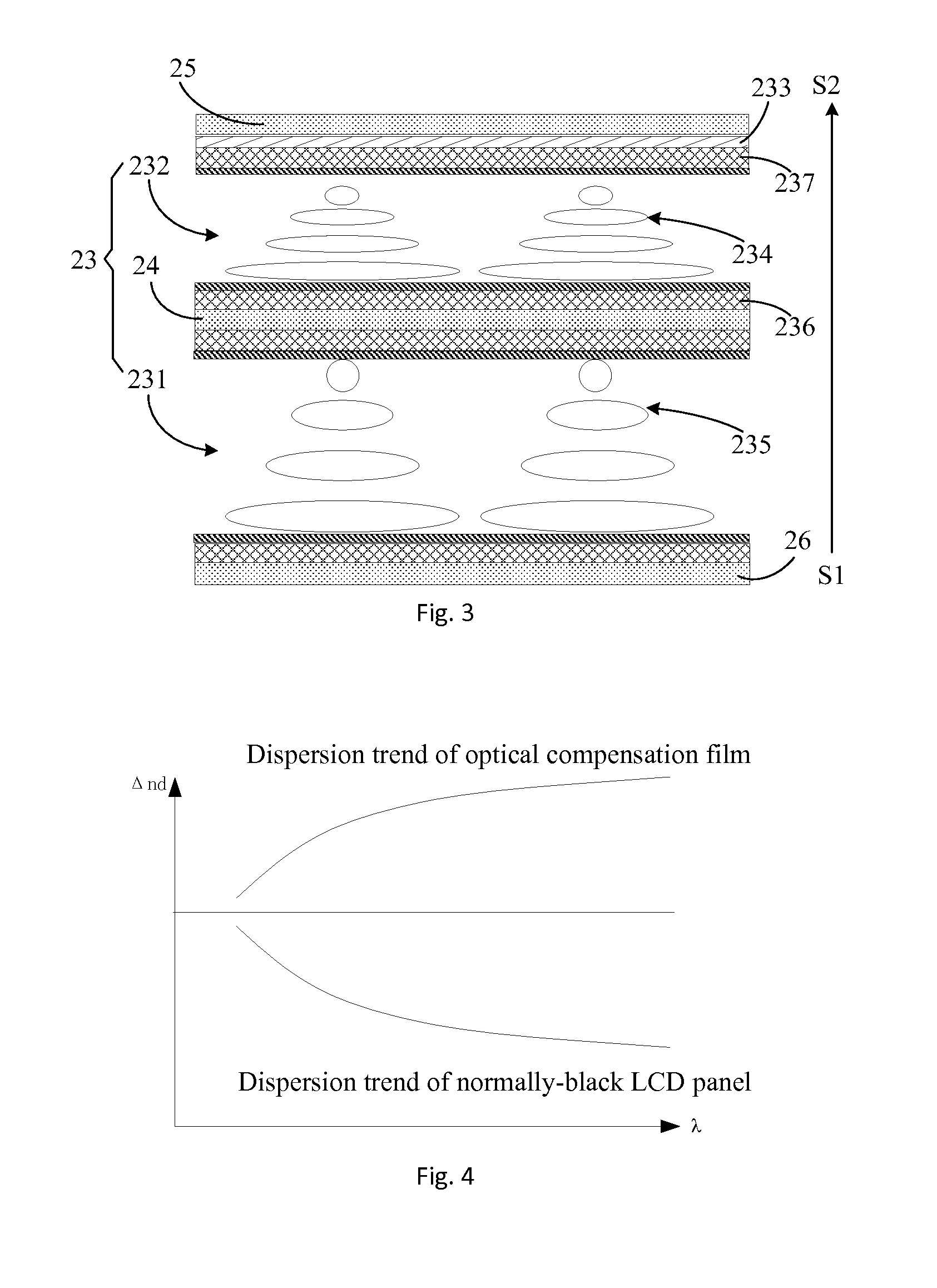
[0041]Please refer to FIG. 3, which is a diagram showing a part of the shutter glasses 20 shown in FIG. 2. In FIG. 3, the LCD panel 23 comprises a normally-white LCD panel 231 and a normally-black LCD panel 232. The thickness of the normally-black LCD panel 232 is not the same as the thickness of the normally-white LCD panel 231.

[0042]The shutter glasses 20 further comprises a first polarizer 24, a second polarizer 25, and...


PUM

PropertyMeasurementUnit
thicknessaaaaaaaaaa
optical axisaaaaaaaaaa
luminanceaaaaaaaaaa

Abstract

The present invention discloses shutter glasses and a 3D display system. The shutter glasses include a first polarizer, a second polarizer, a normally-white LCD panel, and a normally-black LCD panel. A thickness of the normally-white LCD panel is not the same as a thickness of the normally-black LCD panel, and an optical compensation film is installed between the first polarizer and the liquid crystal layer of the normally-black LCD panel and / or between the second polarizer and the liquid crystal layer of the normally-black LCD panel in order to compensate for a dispersion occurred when the liquid crystal layer of the normally-black LCD panel is in a dark mode. In this way, the present invention can not only shorten the response time of the shutter glasses to reduce the power consumption, but also reduce the 3D crosstalk.

Description

BACKGROUND OF THE INVENTION[0001]1. Field of the Invention[0002]The invention relates to display techniques, and more particularly, to a shutter glasses and a 3D display system.[0003]2. Description of the Prior Art[0004]In the age of high-definition TV, a 3D mode has become a preferred function of a big-size TV. In general, specific glasses are required when a user watches the 3D image on the 3D TV. The 3D TVs can be categorized into two categories, shutter-type 3D TV and polarization-type 3D TV.[0005]The shutter-type 3D TV requires a shutter glasses having an LCD having a 120 Hz or higher refresh rate to show the 3D images. The basic theory of the shutter glasses is: When a left-eye image is being shown, the right-eye of the shutter glasses is closed, and when a right-eye image is being shown, the left-eye of the shutter glasses is closed. In this way, the left-eye images and the right-eye images can be separately viewed by single eye such that the user can feel the 3D effect.[0006...

Claims


Application Information

Patent Timeline
Patent Type & Authority Patents(United States)
IPC IPC(8): G02F1/1335H04N13/04
CPCH04N13/0434H04N2213/001H04N13/341H04N13/337G02B30/25
Inventor HE, JHEN-WEI
Owner TCL CHINA STAR OPTOELECTRONICS TECH CO LTD
Why Eureka
Try Eureka