Method of manufacturing piezoelectric actuator

a piezoelectric actuator and actuator technology, applied in the direction of piezoelectric/electrostrictive transducers, generators/motors, transducer types, etc., can solve the problems of high fabrication cost, burrs or dimples, and the associated problem of productivity, so as to achieve the effect of efficient manufacturing of piezoelectric actuators

Inactive Publication Date: 2015-03-17
SEIKO INSTR INC
View PDF3 Cites 0 Cited by
  • Summary
  • Abstract
  • Description
  • Claims
  • Application Information

AI Technical Summary

Benefits of technology

[0010]In view of the foregoing, the present invention has been made. It is an object of the present invention to provide a method of efficiently manufacturing desired piezoelectric actuators having vibrating bodies whose vibrational characteristics are affected less by the machining accuracy than heretofore and thus the driving characteristics of the piezoelectric actuators are affected less.

Problems solved by technology

Since the conventional piezoelectric actuators have been assembled one by one, the productivity is associated with problems.
Additionally, fabrication costs have been high.
With any technique, there arises the problem that formation of burrs or dimples results.
Therefore, a burr left on the vibrator may drag along the moving body, or the burr may add to the mass, thus affecting the amplitude of the vibration.
This may deteriorate the driving performance.
This may deform the vibrator.

Method used


Image

  • Method of manufacturing piezoelectric actuator
  • Method of manufacturing piezoelectric actuator
  • Method of manufacturing piezoelectric actuator

Examples


embodiment 1

[0043]Embodiment 1 of the present invention is described in detail by referring to FIGS. 1, 4 to 8, and 12.

[0044]In Embodiment 1, an example is given in which a vibrating body plate, a moving body plate, and a pressure application member plate (if necessary) are stacked on top of each other to manufacture at least one piezoelectric actuator assembly and then piezoelectric actuators are separated to manufacture piezoelectric actuators.

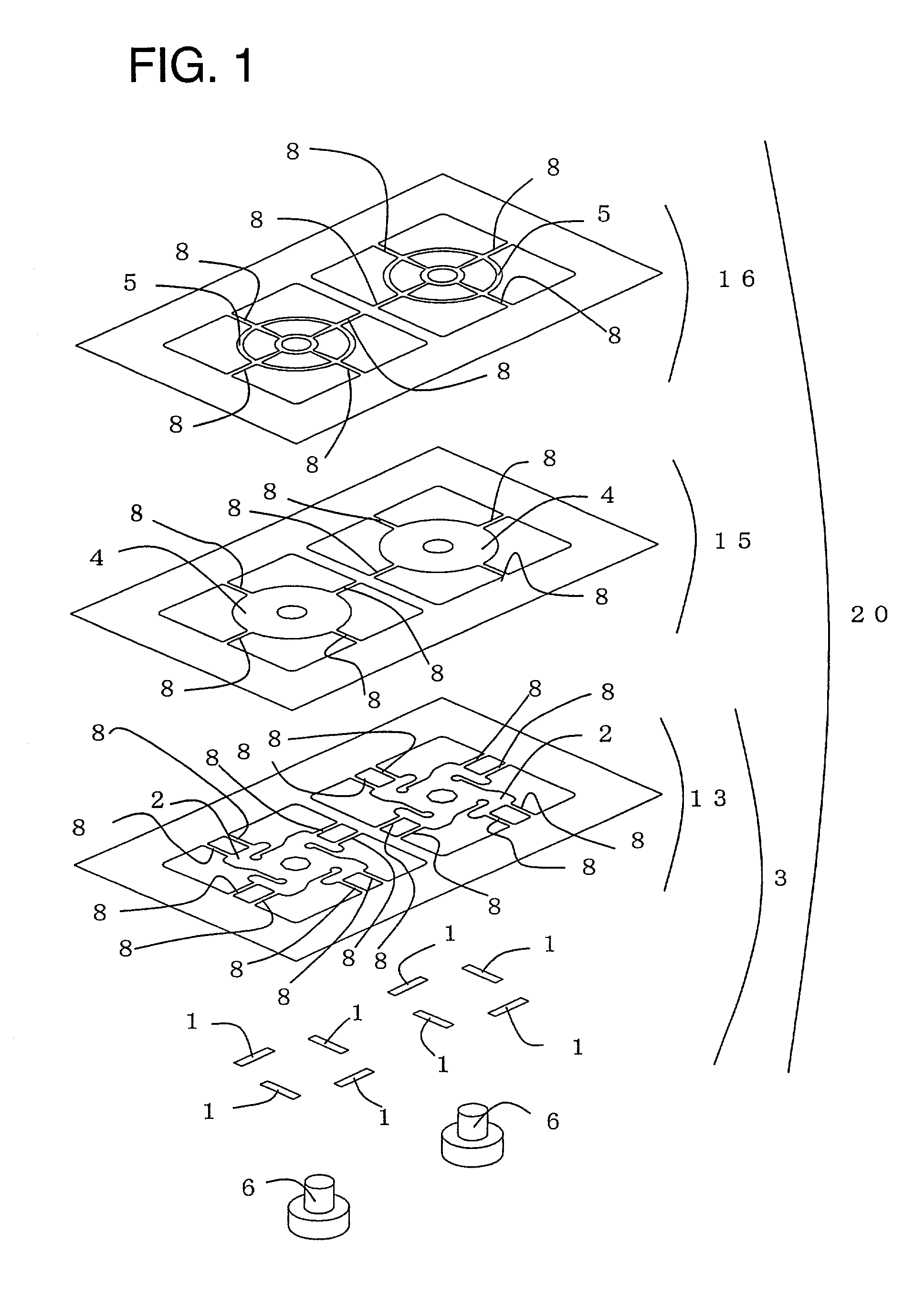
[0045]FIG. 12 is a block diagram showing the structure of the second piezoelectric actuator assembly in accordance with Embodiment 1 to which the present invention is applied.

[0046]The second piezoelectric actuator assembly comprises a first support member or vibrating body plate 13 having vibrating bodies 3 each including a piezoelectric body 1 and a vibrator 2, a second support member or moving body plate 15 having moving bodies 4 for making contact with the vibrating bodies 3 to move them, and a third support member or pressure application member pla...

second embodiment

[0073]Embodiment 2 of the present invention is described in detail by referring to FIGS. 10 and 11.

[0074]In Embodiment 2, an example of fabrication step is given in which vibrating bodies are cut from a vibrating body plate at vibrational nodes, and then the vibrating bodies, moving bodies, and pressure application members (if necessary) are stacked on top of each other.

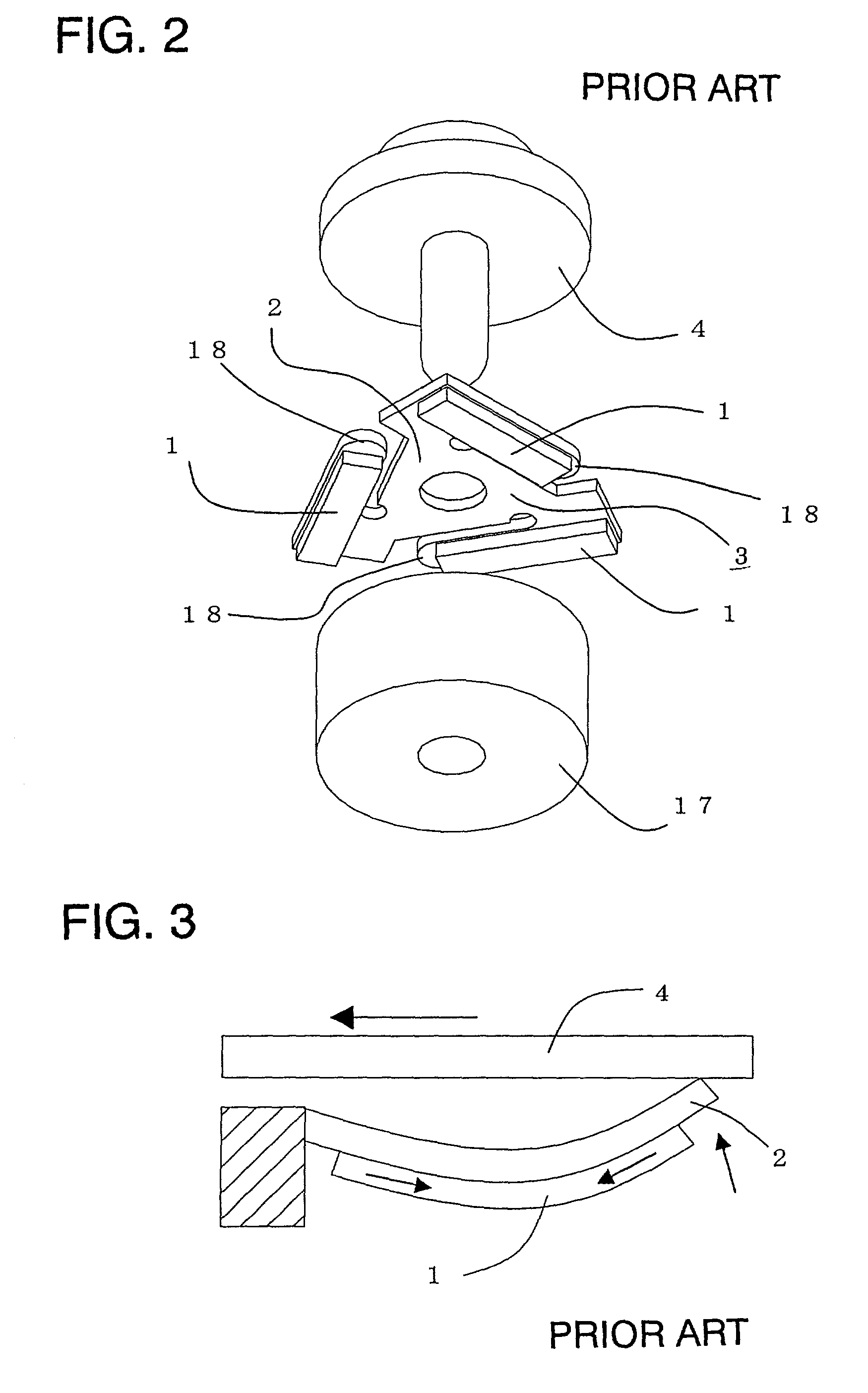
[0075]FIG. 10 shows the structure of a piezoelectric actuator in accordance with Embodiment 2. The piezoelectric actuator comprises a piezoelectric vibrating body 21 having a vibrator 2 stuck to a piezoelectric body 1, a moving body 4 for making contact with a vibrating body 3 to move it, a pressure application member 5 for applying appropriate pressure to the vibrating body 3 and to the moving body 4, and a guide member 6 for guiding the direction of movement of the moving body 4. The vibrator 2 shown in FIG. 10 has been already cut off at the connector portions formed at vibrational nodes 7 of the vibrators 2 shown...


PUM

PropertyMeasurementUnit
resilientaaaaaaaaaa
pressureaaaaaaaaaa
vibrationalaaaaaaaaaa

Abstract

In a method of manufacturing piezoelectric actuators, a vibrating body plate supporting vibrating bodies at vibrational nodes thereof and a moving body plate having moving bodies are provided. Each of the vibrating bodies has a vibrator and a piezoelectric body mounted on the vibrator. The vibrating body plate and the moving body plate are stacked over one another to provide a piezoelectric actuator assembly. The piezoelectric actuator assembly is then cut at the vibrational nodes of the vibrating bodies to provide individual piezoelectric actuators.

Description

FIELD OF THE INVENTIONBackground of the Invention[0001]The present invention relates to a method of manufacturing piezoelectric actuators used in devices such as watches, clocks, cameras, printer, and information storage devices.BACKGROUND INFORMATION[0002]A piezoelectric body produces a distortion when an electrical input is applied. This is referred to as the inverse piezoelectric effect. Features of this piezoelectric body include high output, high response, and non-magnetism. A high-output actuator can be fabricated using a piezoelectric body.[0003]In the past, components of piezoelectric actuators have been machined and assembled one by one by etching or using an NC (numerical control) machine or the like. A specific known example of such a piezoelectric actuator is a piezoelectric micromotor (The Institute of Electrical Engineers of Japan, 15th Sensor Symposium, TECHNICAL DIGEST, pp. 181-184, 1997). FIG. 2 is an assembly view of this piezoelectric micromotor. This piezoelectri...

Claims


Application Information

Patent Timeline
Patent Type & Authority Patents(United States)
IPC IPC(8): H04R17/00H02N2/00H01L41/09
CPCH02N2/0015H02N2/103H02N2/22H04R17/00Y10T29/49789Y10T29/42Y10T29/49126
Inventor WATANABE, SATOSHISATO, TATSUROTANI, KAZUOSHINOHARA, YOKO
Owner SEIKO INSTR INC
Why Eureka
Try Eureka