Automatic choke apparatus for engine

a choke apparatus and automatic technology, applied in mechanical devices, machines/engines, electric control, etc., can solve the problems of inability to mount the bimetal at a high-temperature portion of the muffler, limited mounting condition of the bimetal in the vicinity of the muffler, and difficulty in opening the choke valve, so as to prevent the incomplete combustion of the engine caused by excessive fuel and suppress the temperature drop of the exhaust gas

Inactive Publication Date: 2015-03-17
SUBARU CORP
View PDF32 Cites 2 Cited by
  • Summary
  • Abstract
  • Description
  • Claims
  • Application Information

AI Technical Summary

Benefits of technology

[0008]An object of the present invention is to rapidly heat the bimetal, even when the mounting position of the bimetal is limited.
[0014]According to the present invention, the bypass channel is provided for allowing the expansion chambers to be communicated with each other in such a manner that the connection channel is bypassed. Therefore, the exhaust gas can be supplied to the expansion chamber near the bimetal, while the temperature drop of the exhaust gas can be suppressed. Consequently, even when the bimetal is disposed in the vicinity of the expansion chamber at the downstream side, the high-temperature exhaust gas can be guided from the expansion chamber at the upstream side through the bypass channel. Accordingly, the bimetal can be promptly heated immediately after the start of the engine. Accordingly, the choke valve can be promptly controlled after the start of the engine, whereby the incomplete combustion of the engine caused by excessive fuel can be prevented.

Problems solved by technology

However, it is difficult to open the choke valve according to the completion of the warm-up, depending upon a mounting condition of a bimetal.
The mounting condition of the bimetal disposed in the vicinity of the muffler is limited by a layout of an intake / exhaust system or a shape of an engine.
When there is a great variation in the temperature distribution in the muffler, and the mounting position of the bimetal is limited, it is impossible to mount the bimetal at a high-temperature portion of the muffler.
Therefore, it is difficult to rapidly heat the bimetal after the start of the engine.
The delay in the release of the choke valve due to the delay in heating the bimetal might cause an incomplete combustion of the engine due to excessive fuel.

Method used


Image

  • Automatic choke apparatus for engine
  • Automatic choke apparatus for engine
  • Automatic choke apparatus for engine

Examples


Embodiment Construction

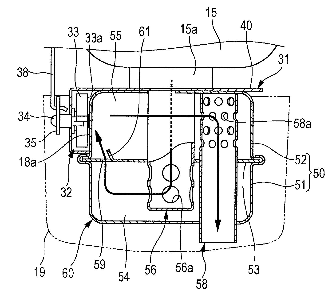
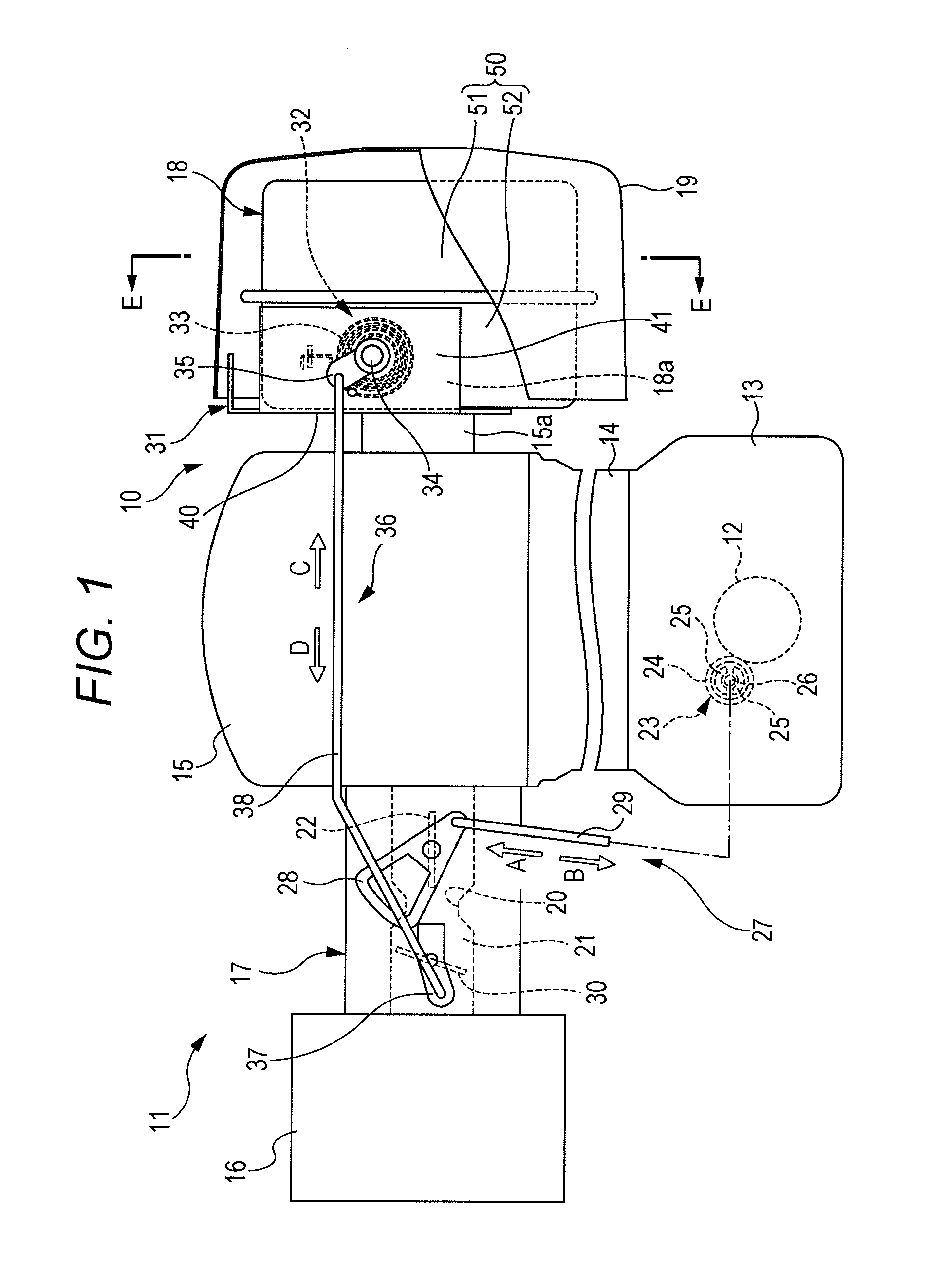
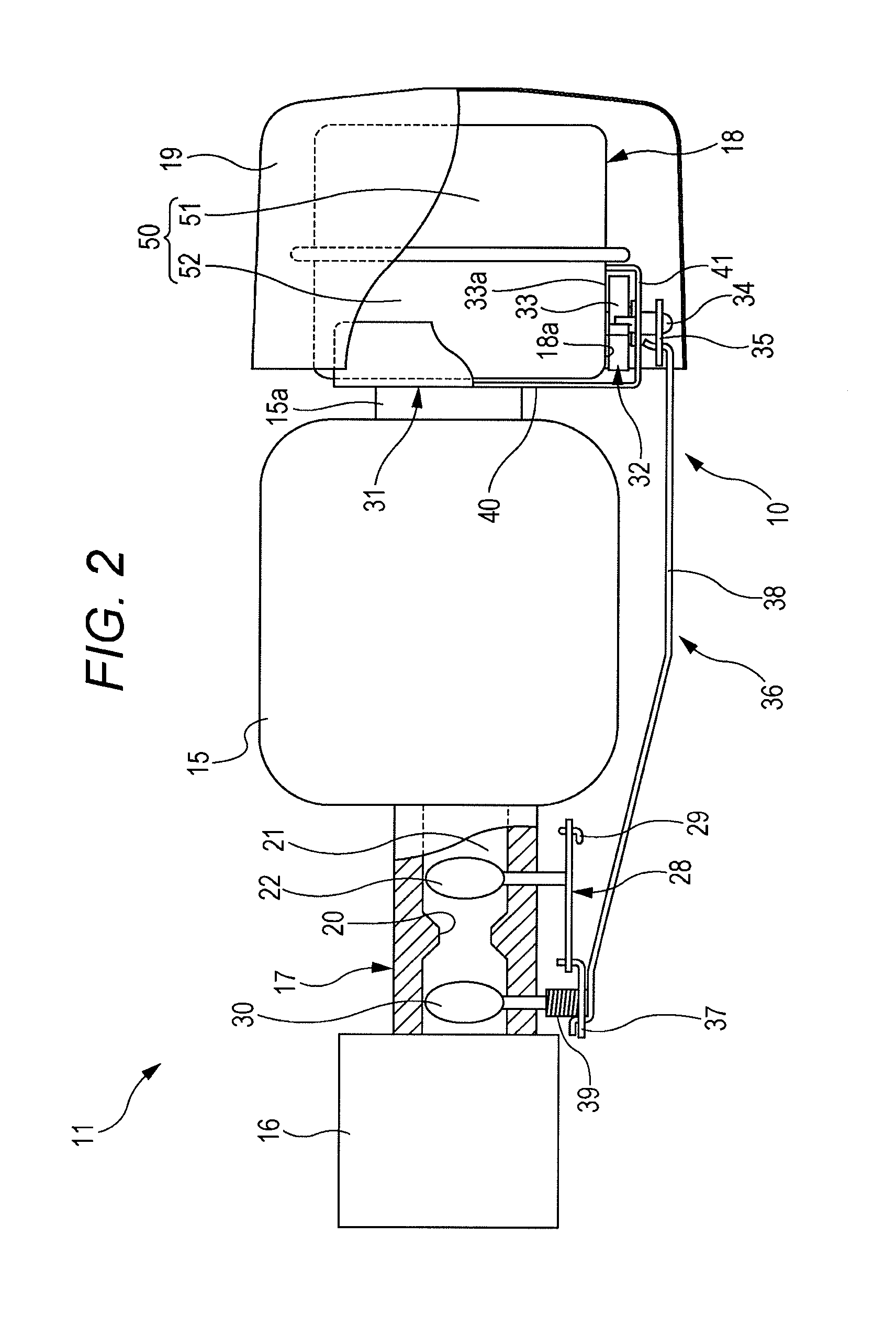
[0026]Embodiments of the present invention will be explained in detail below with reference to the drawings. FIG. 1 is a side view schematically illustrating an engine 11 provided with an automatic choke apparatus 10 according to one embodiment of the present invention. FIG. 2 is a plan view schematically illustrating the engine 11 in FIG. 1 as viewed from top. As illustrated in FIGS. 1 and 2, the engine 11 includes a crankcase 13 that stores a crankshaft 12. A cylinder 14 is attached at an upper end of the crankcase 13, and a cylinder head 15 is mounted to an upper end of the cylinder 14. An air cleaner 16 and a carburetor 17, which constitute an intake system, are connected to an unillustrated intake port of the cylinder head 15. Further, a muffler 18 constituting an exhaust system is connected to an unillustrated exhaust port of the cylinder head 15. A muffler cover 19 is attached to the muffler 18.

[0027]An intake channel 21 provided with a venturi portion 20 is formed on the car...


PUM


Abstract

There is provided an automatic choke apparatus for an engine. A bimetal that is coupled to a choke valve of an intake system is provided in the vicinity of an outer wall face of a muffler. The muffler is divided into a first expansion chamber and a second expansion chamber across a partition plate. An exhaust hole that allows the expansion chambers to be communicated with each other is formed at the lower part of the partition plate. An exhaust gas is guided from the upstream first expansion chamber toward the downstream second expansion chamber through the exhaust hole. A bypass hole is formed at an upper part of the partition plate in such a manner that that the expansion chambers are communicated with each other as bypassing the exhaust hole. The bypass hole is open to the vicinity of the outer wall face opposite to the bimetal.

Description

CROSS-REFERENCE TO RELATED APPLICATIONS[0001]The present application claims priority from Japanese Patent Application No. 2011-072869 filed on Mar. 29, 2011, the entire contents of which are hereby incorporated by reference.BACKGROUND OF THE INVENTION[0002]1. Field of the Invention[0003]The present invention relates to an automatic choke apparatus for an engine, the automatic choke apparatus utilizing heat of an exhaust system so as to operate a choke valve in an intake system.[0004]2. Description of Related Art[0005]A choke valve is provided to a carburetor, which constitutes an intake system of an engine, in order to enhance starting performance of the engine at a low temperature. An intake air amount is reduced by closing the choke valve, whereby an air-fuel mixture can be thickened. Accordingly, the engine can satisfactorily be started. As described above, when the engine is started, the choke valve is closed to thicken the air-fuel mixture. Therefore, it is necessary to open th...

Claims


Application Information

Patent Timeline
Patent Type & Authority Patents(United States)
IPC IPC(8): F01N5/02F02M1/08F01N1/08F02M1/10
CPCF02M1/10F01N1/084F01N5/02Y02T10/16Y02T10/12
Inventor FURUYA, AKIRA
Owner SUBARU CORP
Why Eureka
Try Eureka