Vibration damping insulator for fuel injection valve

a technology of vibration damping and fuel injection valve, which is applied in the direction of fuel injection apparatus, charge feed system, engine sealing arrangement, etc., can solve the problems of fuel leakage, thermal deformation, and various vibrations that accompany the operation of the internal combustion engine, and the relative positions of the tolerance associated with the assembly in production, so as to increase the stiffness of the tolerance ring itself, improve the durability of the tolerance ring, and improve the sealing

Active Publication Date: 2015-03-17
TOYOTA JIDOSHA KK +1
View PDF39 Cites 7 Cited by
  • Summary
  • Abstract
  • Description
  • Claims
  • Application Information

AI Technical Summary

Benefits of technology

[0011]According to this configuration, the stiffness of the tolerance ring itself is increased by the sleeve section provided integrally thereto to extend therefrom, whereby the durability of the tolerance ring against a force that is received thereby from the tapered surface of the fuel injection valve and acts in a manner enlarging the opening of the tolerance ring is improved. Thus, warping of the tolerance ring is prevented from occurring, and a position at which the tapered surface of the fuel injection valve abuts the tolerance ring is maintained. That is, the fuel injection position of the fuel injection valve with respect to the combustion chamber is suitably maintained, and the combustion state is appropriately maintained as well.
[0029]According this configuration, the relative position of the tolerance ring, which is not easy to be strongly joined to the elastic member, with respect to the elastic member is defined by the plate from the inner circumference. This makes it possible to facilitate appropriate stacking of the tolerance ring onto the elastic member. As a result, improvement in feasibility of this vibration insulator is enabled.

Problems solved by technology

When a fuel pressure supplied to the fuel injection valve through the delivery pipe has changed due to injection or stopping of the fuel, vibration based on the change in fuel pressure and vibration accompanying the operation of the fuel injection valve usually occur to the above fuel injection valve.
Therefore, changes in the relative positions thereof, which are caused by, for example, tolerances associated with production or processing of these parts, tolerances associated with assembly in the production, thermal deformation, and various vibrations that accompany the operation of the internal combustion engine, are unavoidable.
Further, such positional deviation causes problems such as partial slack of an O-ring at the proximal end of the fuel injection valve, the O-ring serving to prevent fuel leakage between the fuel injection valve and the delivery pipe (fuel injection valve cup).
Therefore, the positional deviation may possibly cause fuel leakage.

Method used


Image

  • Vibration damping insulator for fuel injection valve
  • Vibration damping insulator for fuel injection valve
  • Vibration damping insulator for fuel injection valve

Examples


first embodiment

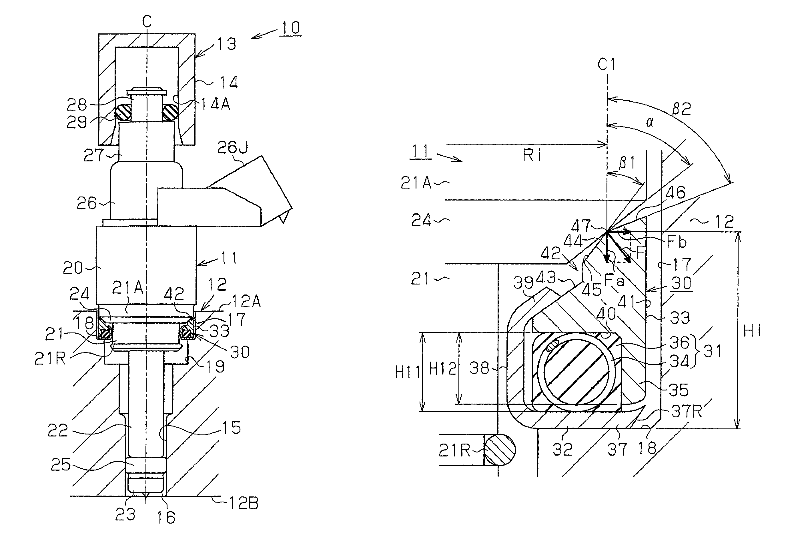
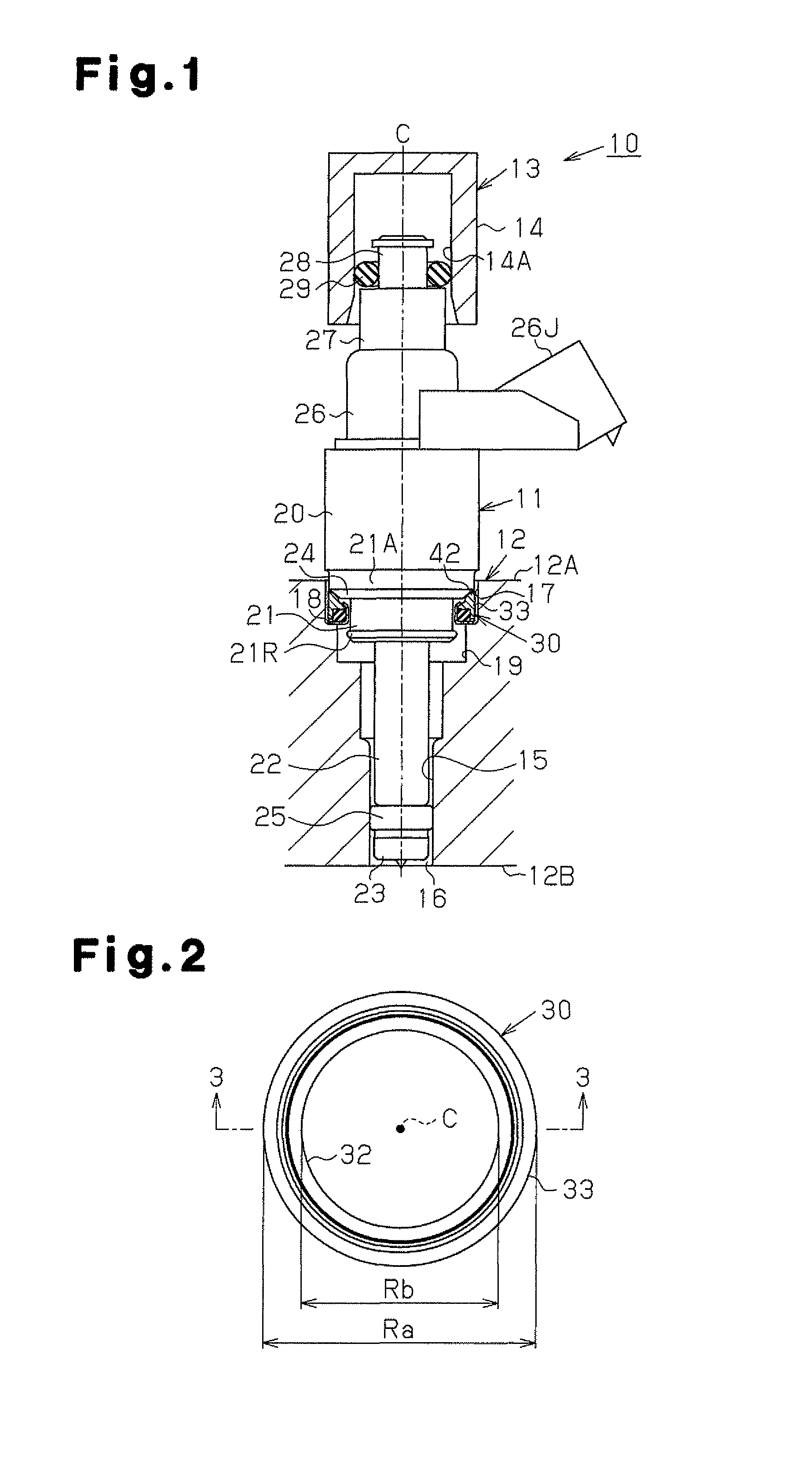
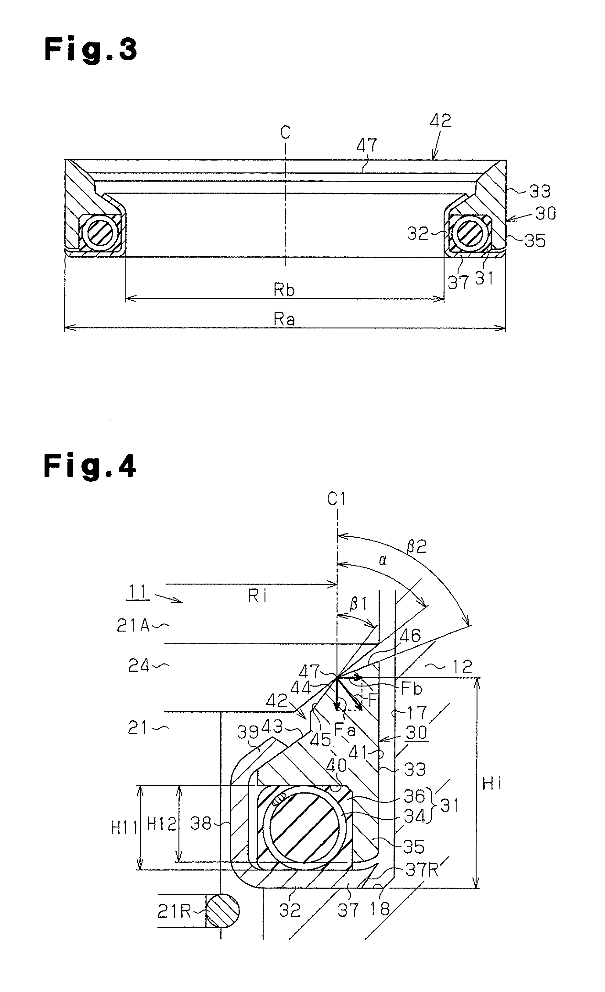
[0046]FIGS. 1 to 5 illustrate a vibration insulator according to a first embodiment of the present invention.

[0047]FIG. 1 is a diagram schematically showing a schematic structure of a fuel injection system to which a vibration insulator of this embodiment is applied. FIG. 2 is a diagram showing the structure of the vibration insulator in a flat plane. FIG. 3 is a diagram showing the structure of the vibration insulator in a cross-sectional view. FIG. 4 is a diagram showing the structure of an end face of the vibration insulator in an end view. FIGS. 5(a) and 5(b) are illustrations for illustrating states of compensating movement performed in response to deviation from the center position of the vibration insulator, where FIG. 5(a) is a diagram showing a state where the axis C thereof is centered, and FIG. 5(b) is a diagram showing a state where the axis C thereof is off-center.

[0048]As shown in FIG. 1, a fuel injection system 10 is provided with a fuel injection valve 11. While a pa...

second embodiment

[0096]FIG. 6 is an end view showing the structure of a vibration insulator 30 according to a second embodiment of the present invention. Since this embodiment differs from the first embodiment in structure of the vibration insulator 30 but the other structures are the same, differences from the first embodiment are mainly described, and description of members similar to those of the first embodiment is omitted by assigning the same reference signs thereto, for illustrative purposes.

[0097]As shown in FIG. 6, the vibration insulator 30 is formed by sequentially stacking a vibration damping member 31 and the tolerance ring 33 on a plate bottom section 37 of a plate 32.

[0098]The vibration damping member 31 includes: an elastic member 36A formed of rubber or the like, which is similar to the elastic member 36 described in the first embodiment; and an annular coil spring 34 embedded in the elastic member 36A. In this embodiment, the outer circumferential surface of the elastic member 36A ...

third embodiment

[0104]FIG. 7 is an end view showing the structure of a vibration insulator 30 according to a third embodiment of the present invention. Since this embodiment differs from the first embodiment in structure of the vibration insulator 30 but the other structures are the same, differences from the first embodiment are mainly described, and description of members similar to those of the first embodiment is omitted by assigning the same reference signs thereto, for illustrative purposes.

[0105]As shown in FIG. 7, the vibration insulator 30 is formed by sequentially stacking a vibration damping member 31 and a tolerance ring 33 on a plate bottom section 37 of a plate 32.

[0106]The vibration damping member 31 includes: an elastic member 362 formed of rubber or the like, which is similar to the elastic member 36 described in the first embodiment; and an annular coil spring 34 embedded in the elastic member 36B.

[0107]The tolerance ring 33 includes: an inner sleeve section 35B extending toward t...


PUM


Abstract

A fuel injection valve is mounted in a cylinder head by being inserted in an insertion hole provided in the cylinder head. A shoulder section is provided at the inlet portion of the insertion hole to be expanded in an annular shape. The fuel injection valve is provided with a stepped section expanded in diameter in a tapered manner to have a tapered surface facing the shoulder section. A vibration insulator is disposed between the stepped section and the shoulder section. The vibration insulator is provided with a circular annular tolerance ring making contact with the tapered surface of the fuel injection valve. A circular annular sleeve section coaxial with the tolerance ring is integrally formed on the tolerance ring to extend from the surface of a portion of the tolerance ring, the portion not facing the tapered surface of the fuel injection valve.

Description

FIELD OF THE DISCLOSURE[0001]The present invention relates to a vibration insulator for a fuel injection valve. The vibration insulator is configured to damp vibration that occurs in the fuel injection valve, which injects fuel into an internal combustion engine.BACKGROUND OF THE DISCLOSURE[0002]Conventionally, internal combustion engines of one type in which fuel is injected into the inside of a combustion chamber, that is, internal combustion engines of the in-cylinder injection type, for example, have the distal end portion of a fuel injection valve inserted into and supported by an insertion hole of a cylinder head and have the proximal end portion of the fuel injection valve inserted into and supported by a delivery pipe (a fuel injection valve cup), whereby the fuel injection valve is provided across the cylinder head and the delivery pipe. When a fuel pressure supplied to the fuel injection valve through the delivery pipe has changed due to injection or stopping of the fuel, ...

Claims


Application Information

Patent Timeline
Patent Type & Authority Patents(United States)
IPC IPC(8): F02M61/14
CPCF02M61/14F02M2200/858F02M2200/306
Inventor KAMADA, AKIRASUGIYAMA, NATSUKISUMIDA, TOMOKAZUWATANABE, SEIZO
Owner TOYOTA JIDOSHA KK
Why Eureka
Try Eureka