
Irrigant distribution system for flexible electrodes

a flexible electrode and distribution system technology, applied in the field of irrigant distribution system for flexible electrodes, can solve the problems of affecting the effect of coagulation, affecting and limiting the temperature correlation, so as to reduce charring, improve the temperature correlation, and inhibit the formation of coagulum

Active Publication Date: 2015-03-17
ST JUDE MEDICAL ATRIAL FIBRILLATION DIV
View PDF71 Cites 3 Cited by
  • Summary
  • Abstract
  • Description
  • Claims
  • Application Information

AI Technical Summary

Benefits of technology

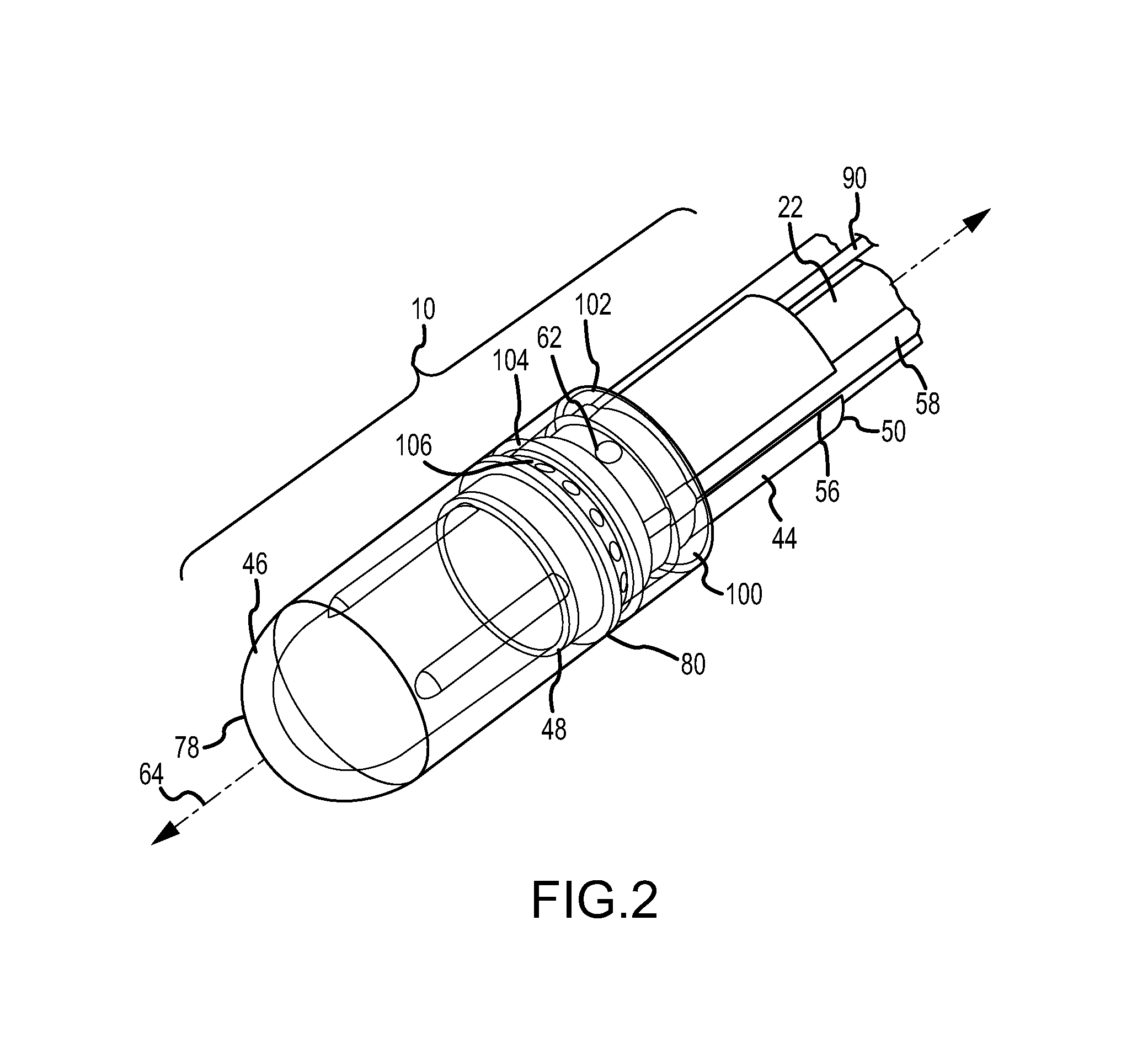
The patent is about improving the temperature correlation between an ablation electrode and the tissue interface, as well as reducing charring and the formation of coagulum during RF ablation. The invention includes a mechanism to irrigate the ablation electrode assemblies and targeted areas in a patient's body with biocompatible fluids, such as saline solution, to enable deeper and greater volume lesions as compared to non-irrigated catheters. The flow of the irrigation fluid is designed to prevent stasis and the formation of coagulum. The electrode conforms to cardiac anatomy to improve energy efficiency during RF ablation. The invention includes an irrigant distribution element comprising an annular ring and a fluid shaping member to improve the fluid flow characteristics of the irrigation fluid.

Problems solved by technology

This lesion disrupts undesirable cardiac activation pathways and thereby limits, corrals, or prevents errant conduction signals that can form the basis for arrhythmias.
During RF ablation, local temperature elevation can result in coagulum formation on the ablation electrode, resulting in an impedance rise.
Not only can this process be time consuming, but it can be difficult to return to the previous location because of the reduced electrical activity in the targeted tissue, which has been previously ablated.
In addition, RF ablation can generate significant heat, which, if not controlled, can result in excessive tissue damage, such as tissue charring, steam pop, and the like.

Method used


Image

  • Irrigant distribution system for flexible electrodes
  • Irrigant distribution system for flexible electrodes
  • Irrigant distribution system for flexible electrodes

Examples


Embodiment Construction

[0026]The instant disclosure generally relates to irrigated ablation electrode assemblies. For purposes of this description, similar aspects among the various embodiments described herein will be referred to by similar reference numbers. As will be appreciated, however, the structure of the various aspects can be different among the various embodiments.

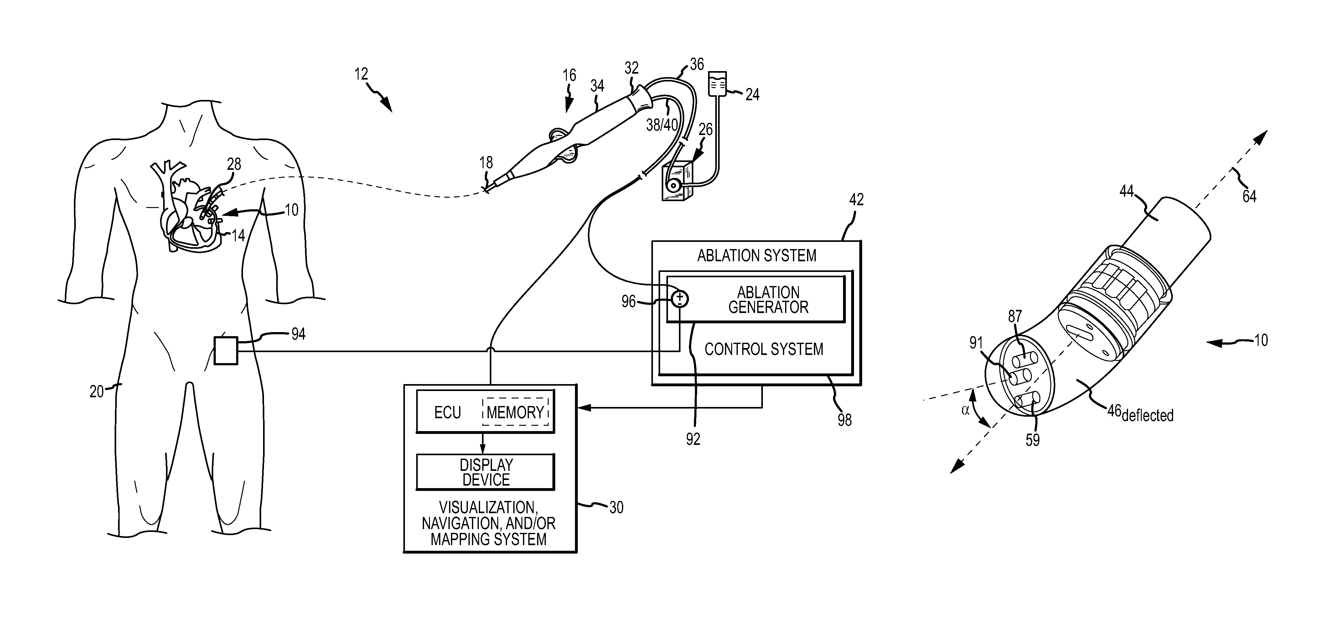
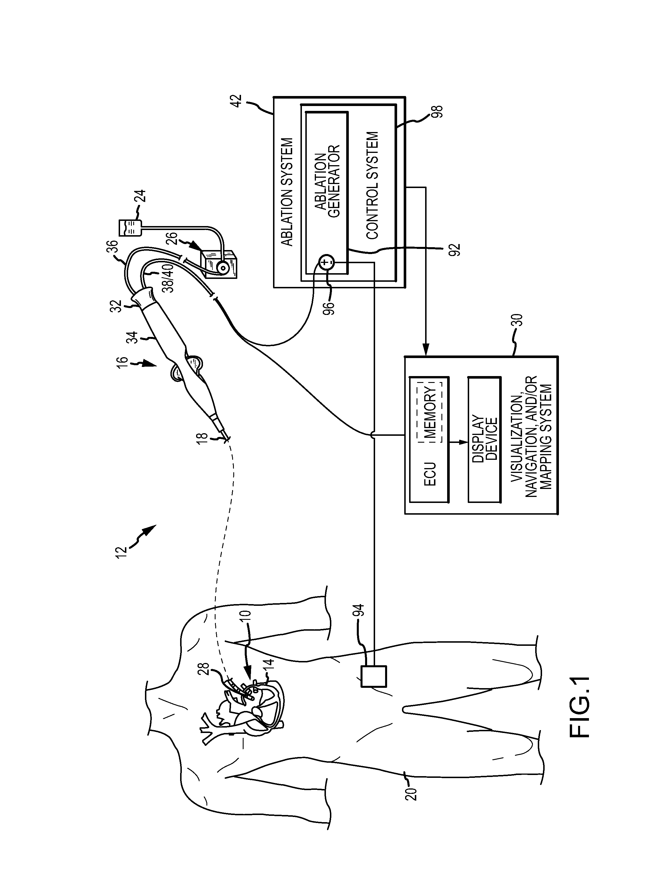
[0027]Referring to FIG. 1, an ablation electrode assembly 10 can comprise part of an irrigated catheter system 12 for examination, diagnosis, and / or treatment of internal body tissues (e.g., targeted tissue areas 14). In an exemplary embodiment, the irrigated catheter assembly can comprise an ablation catheter 16 (e.g., radio frequency (RF), cryoablation, ultrasound, etc.). The instant disclosure generally refers to RF ablation electrodes and electrode assemblies, but it is contemplated that the instant disclosure is equally applicable to any number of other ablation electrodes and electrode assemblies where the temperature of the dev...


PUM


Abstract

Ablation electrode assemblies having a longitudinal axis include an electrode core member; an electrode shell; and an irrigant distribution element. The electrode core member comprises a thermal insulator and has a first end; a second end; and at least one irrigation passageway. The electrode shell comprises an electrically conductive material, defines an inner volume, and has a first end; and a second end. The second end of the electrode shell is configured for connection to the first end of the electrode core member. The electrode shell is sufficiently flexible for deflection of the distal end of the electrode shell relative to the longitudinal axis of the ablation electrode assembly. The irrigant distribution assembly comprises a first end; and a second end, wherein the second end of the irrigant distribution element defines a circumferential irrigation port between the irrigant distribution element and the electrode core member.

Description

CROSS-REFERENCE TO RELATED APPLICATIONS[0001]This application is a continuation-in-part of U.S. patent application Ser. No. 13 / 151,750 entitled “Multi-rate Fluid Flow and Variable Power Delivery for Ablation Electrode Assemblies Used in Catheter Ablation Procedures,” filed 2 Jun. 2011 (the '750 application), which is a continuation-in-part of U.S. patent application Ser. No. 12 / 979,803 entitled “Ablation Electrode Assemblies and Methods for Using Same,” filed 28 Dec. 2010 (the '803 application), now pending; and this application is a continuation-in-part of U.S. patent application Ser. No. 12 / 971,645 entitled “Irrigated Ablation Electrode Assemblies,” filed 17 Dec. 2010 (the '645 application), now U.S. Pat. No. 8,814,857. The '750 application, the '803 application, and the '645 application are all hereby incorporated by reference in their entirety as though fully set forth herein.BACKGROUND OF THE INVENTION[0002]a. Field of the Invention[0003]The instant disclosure relates generally...

Claims


Application Information

Patent Timeline
Patent Type & Authority Patents(United States)
IPC IPC(8): A61B18/18A61B17/00A61B18/00A61B18/02A61B18/14A61N7/02
CPCA61B18/1492A61B18/02A61B2017/00323A61N7/022A61B2018/00702A61B2018/00791A61B2218/002A61B2018/00345A61B2018/1465
Inventor CHRISTIAN, STEVEN C.
Owner ST JUDE MEDICAL ATRIAL FIBRILLATION DIV
Learn More