Coordinate measuring device having automatic target detection

a technology of automatic target detection and measuring device, which is applied in the direction of optical radiation measurement, instruments, spectrometry/spectrophotometry/monochromator, etc., can solve the problem of excited transverse modes in laser diodes, and achieve the effect of simple mechanical structur

Active Publication Date: 2015-03-17
LEICA GEOSYSTEMS AG
View PDF11 Cites 3 Cited by
  • Summary
  • Abstract
  • Description
  • Claims
  • Application Information

AI Technical Summary

Benefits of technology

[0012]It is an object of the invention to provide a coordinate measuring device and a method for operating a coordinate measuring device, of the type mentioned in the introduction, which allow economical production together with precise measurements.
[0027]The invention with the use of a broadband source stands in contrast to conventional designs for the illumination of a target detection device, in which laser light sources are deliberately used in order to achieve high powers. It is found that the design of the illumination is markedly simplified: previously used means for generating decoherence of the laser light are obviated. Although SLEDs cannot be operated with such high light powers like laser diodes can, operation with measurement distances of, for example, up to 160 meters is possible. Although SLEDs are many times more expensive than laser diodes (for example forty times), their use is beneficial overall.
[0035]Owing to the arrangement of the exit and / or entry optics of all the units, a compact unit is provided which can fulfill a multiplicity of functions, while having a simple mechanical structure (only two driven axes). All the units are aligned together with the measuring aid or target. With the two target detection units, measuring aids which have not yet been found can be detected, acquired and tracked in a larger range.

Problems solved by technology

However, the problem arises that a plurality of transverse modes are excited in laser diodes.

Method used


Image

  • Coordinate measuring device having automatic target detection
  • Coordinate measuring device having automatic target detection
  • Coordinate measuring device having automatic target detection

Examples


Embodiment Construction

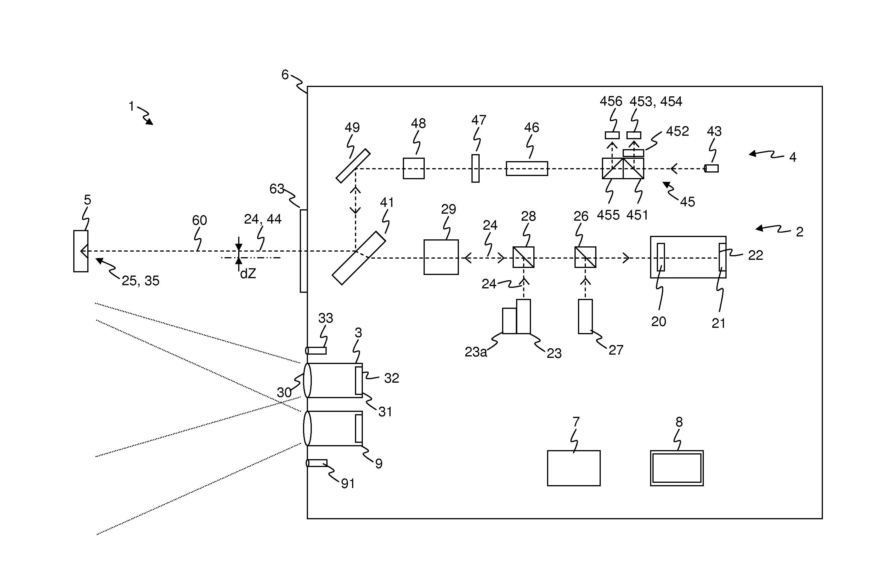
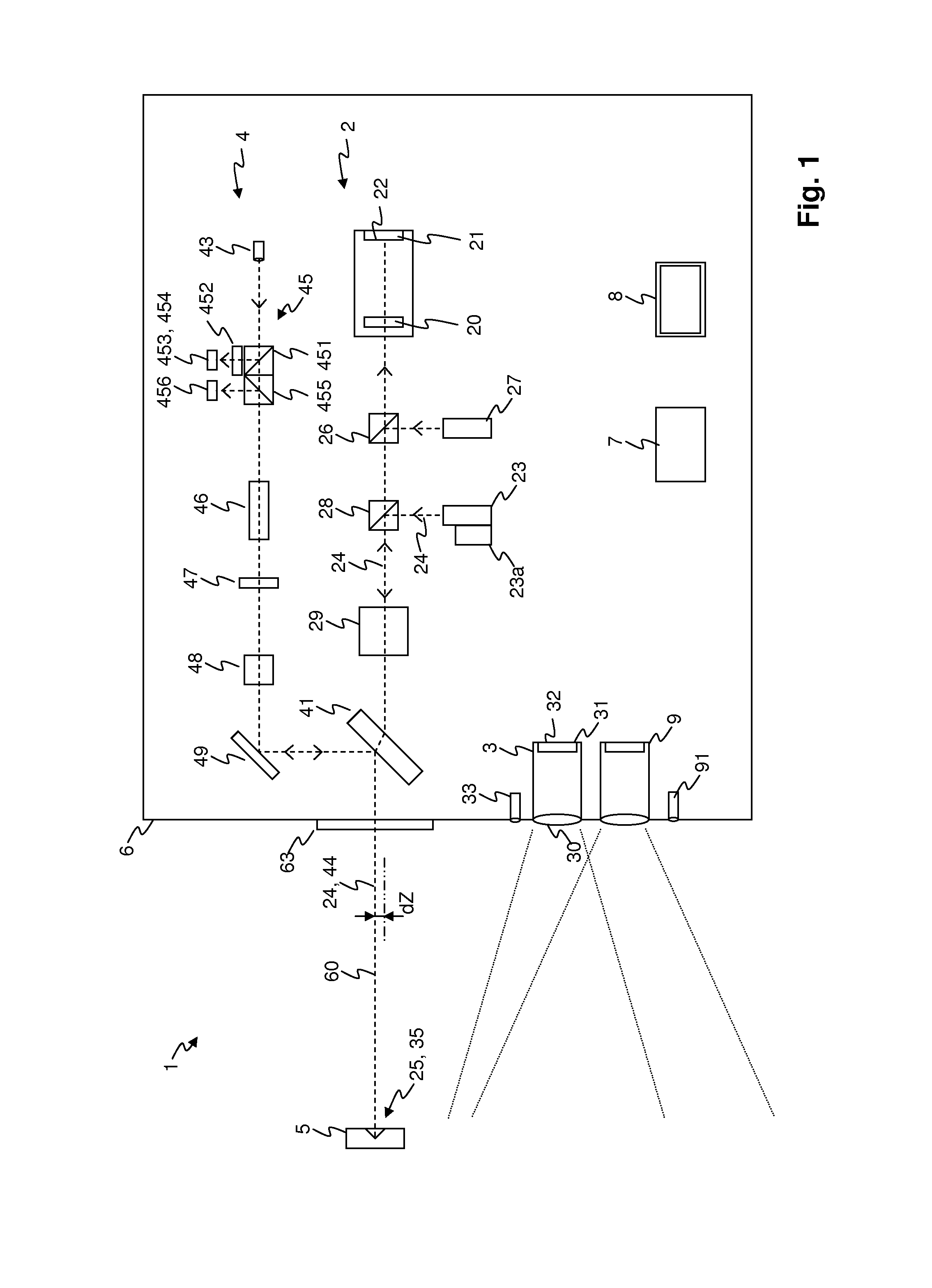
[0048]FIG. 1 schematically shows the beam path in a coordinate measuring device 1 in a preferred embodiment of the invention. The essential elements of the coordinate measuring device 1 are arranged in or on a carrier 6, preferably in a common housing. A fine target detection unit 2 generates a first target beam, preferably an infrared target beam 24, and a distance measuring apparatus 4 generates a measurement light beam 44. The two beams emerge through common exit optics 63, and preferably travel coaxially along a measurement axis 60. Arranged on the carrier, there are furthermore a coarse target detection unit 3 comprising a second light source 33, and a survey camera 9. A closed loop and open loop control unit 7 detects and processes the measurement values of various answers and controls axial position motors for alignment of the carrier 6. A display apparatus 8 shows information about measurements and the device status, and can also display images of one of the image sensors pr...


PUM


Abstract

A coordinate measuring device includes a carrier that can be rotated automatically about two axes and that can be directed toward a measuring aid. The following are arranged on the carrier so as to be able to move together: an optical distance measuring device for measuring the distance to the measuring aid; a light source for emitting light, directly or by means of optical elements, wherein said light is visible as a target point when reflected on the measuring aid; a target detecting unit for determining a position as the position of the imaging of the target point on a position detection sensor. The control apparatus is designed to direct the carrier at the measuring aid by rotating the carrier about the at least two axes of the carrier according to the fine position and the rough position; and the light source is a superluminescent diode (SLED).

Description

BACKGROUND OF THE INVENTION[0001]1. Field of the Invention[0002]The invention relates to a coordinate measuring device and to a method for operating a coordinate measuring device, according to the precharacterizing clauses of the corresponding independent patent claims.[0003]2. Description of Related Art[0004]In order to measure the position of moving target points, coordinate measuring devices are used, often so-called laser trackers. The term laser tracker is intended to mean devices which comprise at least one distance meter operating with a focused laser beam (referred to in the following description as a measurement beam). With the aid of a mirror which can be rotated about two axes, for example, the direction of the measurement beam is adjusted to the target point and recorded by angle transducers assigned to the rotation axes. The target point to be measured is provided with a retro-reflector (in particular corner cube prism or arrangement of three mirrors placed perpendicula...

Claims


Application Information

Patent Timeline
Patent Type & Authority Patents(United States)
IPC IPC(8): G01S7/481G01J5/02G01C15/00G01S17/08G01S17/66G01S17/86
CPCG01S17/66G01C15/002G01S17/08G01S7/4812G01S17/023G01S7/481G01S17/86
Inventor BOECKEM, BURKHARDLUETHI, THOMAS
Owner LEICA GEOSYSTEMS AG
Why Eureka
Try Eureka