Switch-equipped coaxial connector

a coaxial connector, switch-equipped technology, applied in the direction of coupling device connection, coupling device details, printed circuits, etc., can solve the problems of increased size of the whole connector, reduced height, and electrical connectivity, and achieves the effect of maintaining the function of the contact parts, ensuring flexibility, and increasing the span length

Inactive Publication Date: 2015-03-24
DAIICHI SEIKO CO LTD
View PDF13 Cites 11 Cited by
  • Summary
  • Abstract
  • Description
  • Claims
  • Application Information

AI Technical Summary

Benefits of technology

[0008]Therefore, it is an object of the present invention to provide a switch-equipped coaxial connector configured with a simple configuration to be able to well prevent plastic deformation of contacts while avoiding increase in size and well prevent occurrence of failure in electrical connection caused by dust which has entered therein.
[0010]According to the switch-equipped coaxial connector having such a configuration, the path of the elastic beam-like member is extended by the distance of the curved shape of the bent extending part provided in the elastic beam-like member to substantially increase the span length, elasticity of the contact is sufficiently ensured, and occurrence of plastic deformation of the contact is prevented. Moreover, since the bent extending part is provided in the root part of elastic displacement of the elastic beam-like member, stress concentration of the elastic displacement that is to be generated at the root part of the elastic beam-like member is dispersed along the bent extending part, and stress distribution of the entire contact is improved to be more uniformized.
[0011]In this case, since the through hole is formed at least in part of the bent extending part, dispersion of the stress concentration is carried out further better. Also by virtue of this, occurrence of plastic deformation of the contact is prevented, dust which has entered the inside from outside of the equipment falls through the through hole, and electrical conductivity is ensured well.
[0015]According to the switch-equipped coaxial connector consisting of such a configuration, the through hole is extending from the vertex part of the curved shape of the bent extending part. Therefore, dispersion of the above described concentrated stress is efficiently carried out.
[0017]According to the switch-equipped coaxial connector consisting of such a configuration, the fixing force caused by the fixing extended pieces is added to the fixing base part, thereby more stably retaining the entire elastic beam-like member, and the function of the contact parts is maintained well.
[0018]As described above, in the switch-equipped coaxial connector according to the present invention, the bent extending part which substantially increases the span length of the elastic beam-like member is formed to be bent in the elastic beam-like member of the first-side contact, which is extending like a cantilever in the insulating housing, so as to form a curved shape at the root part serving as the part coupled to the fixing base part, and the through hole is formed in the region including at least part of the bent extending part, thereby ensuring flexibility while enhancing elasticity of the contact and preventing permanent deformation of the contact. Meanwhile, electrical conductivity is configured to be ensured well by causing the dust entered the inside from outside of the equipment is caused to fall through the through hole. Therefore, with a simple configuration, plastic deformation of the contact can be prevented well while avoiding increase in size, occurrence of failure in electrical connection caused by dust can be prevented well, and reliability of the switch-equipped coaxial connector can be significantly enhanced at low cost.

Problems solved by technology

However, such a conventional switch-equipped coaxial connector may cause a problem in electrical connectivity since the contacts may undergo plastic (permanent) deformation when the probe (test needle) of the test plug connector is inserted, particularly when it is repeatedly inserted.
However, if the lengths of the contacts are simply increased, the size of the whole connector is increased, which goes against recent demands for downsizing and reduction in height.
Also, there is a problem that minute debris or dust such as insulating matters present in a usage atmosphere may enter the interior through the insertion hole of the probe (test needle) of the test plug connector and cause insufficient electrical connection.

Method used


Image

  • Switch-equipped coaxial connector
  • Switch-equipped coaxial connector
  • Switch-equipped coaxial connector

Examples


Embodiment Construction

[0046]Hereinafter, an embodiment in which a switch-equipped coaxial connector according to the present invention is employed as a circuit test switch will be explained in detail based on drawings.

[0047][Overall Structure of Circuit Test Switch]

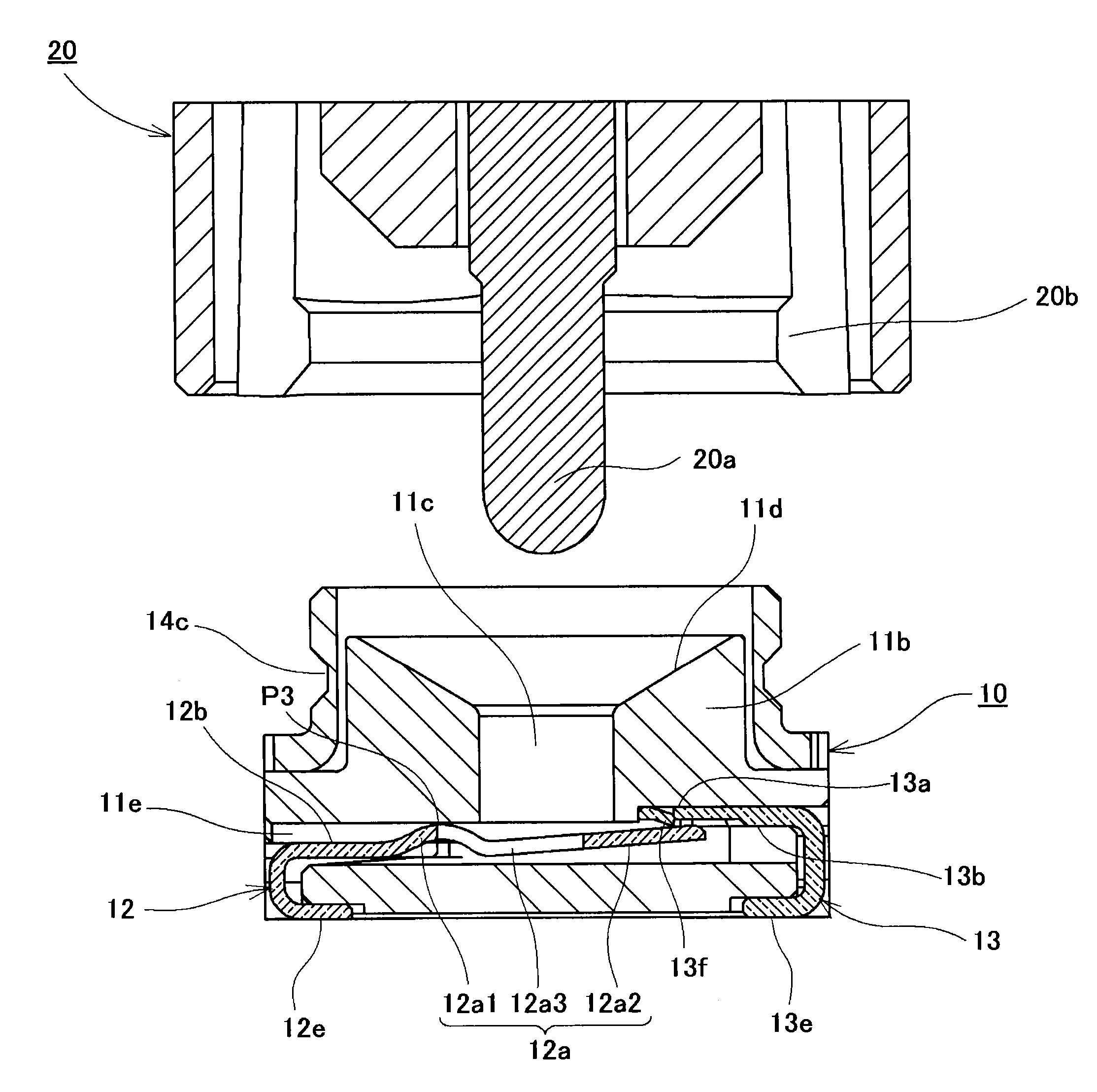
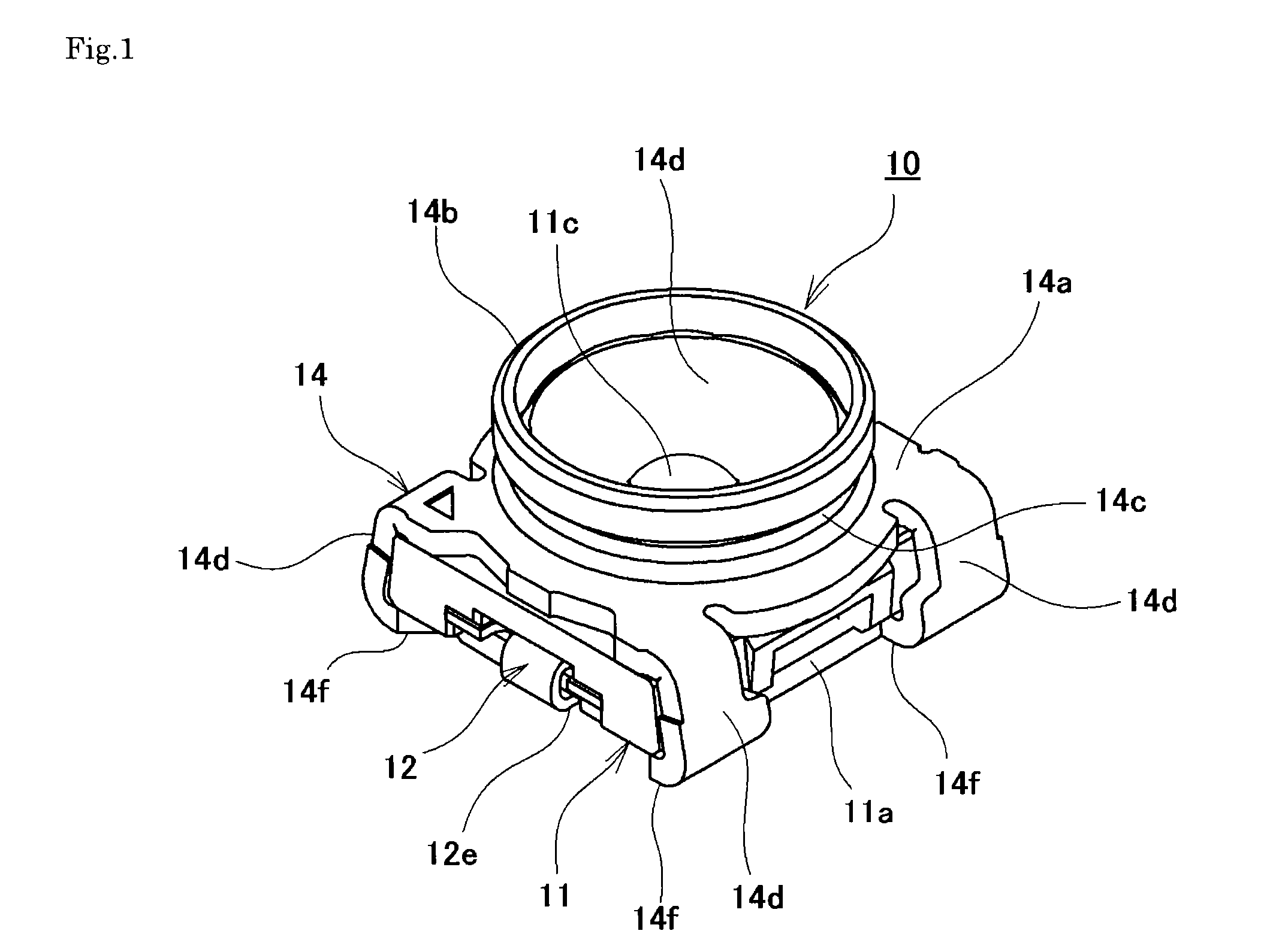
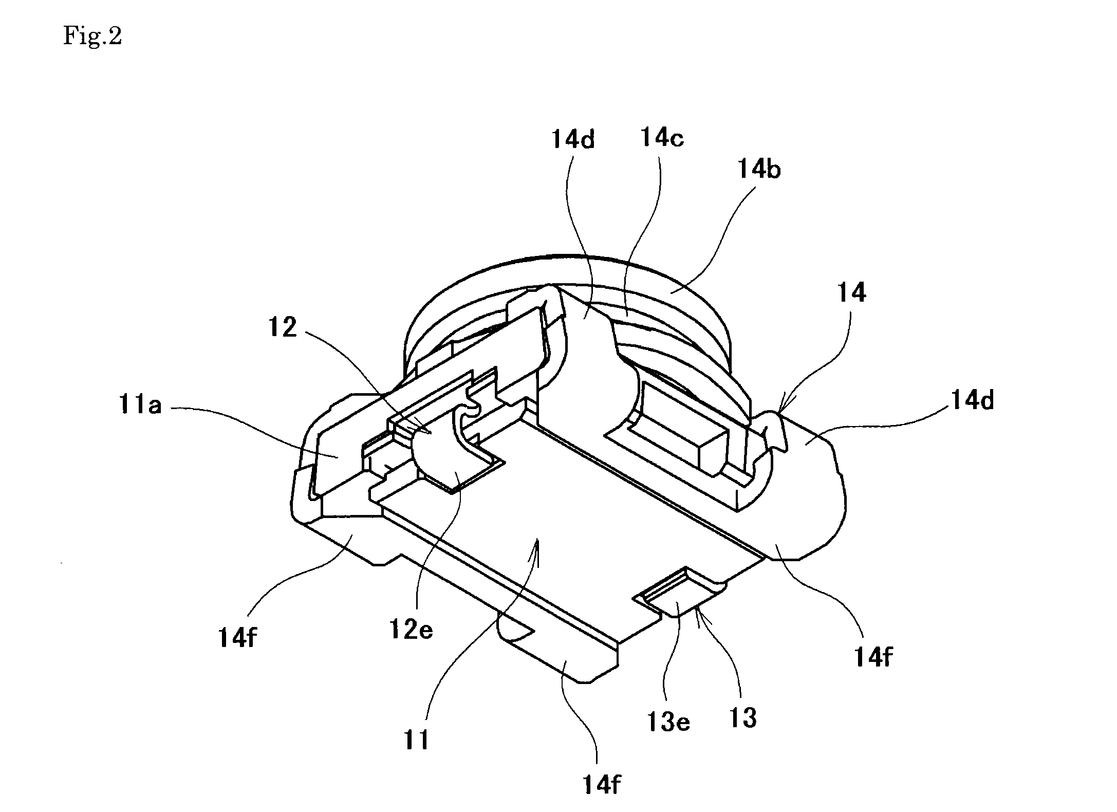
[0048]First, a switch-equipped coaxial connector 10 according to a first embodiment of the present invention shown in FIG. 1 to FIG. 8 is mounted on a wiring board, of which illustration is omitted. A test plug connector 20 (see FIG. 25 to FIG. 27) serving as an opposing connector is configured to be mated with the switch-equipped coaxial connector 10 from the upper side or be removed toward the upper side. More specifically, the test plug connector 20 disposed in the upper side of the switch-equipped coaxial connector 10 is thrust toward the switch-equipped coaxial connector 10 with appropriate force while being held by a hand of an operator, and an attached state in which both of the connectors are mated with each other is obtained as a resu...


PUM


Abstract

With a simple configuration, plastic deformation of contacts can be prevented while avoiding increase in size, and occurrence of failure in electrical connection due to dust can be well prevented. In an elastic beam-like member of a first-side contact extending like a cantilever in an insulating housing, a bent extending part which substantially increases the span length of the elastic beam-like member is formed to be bent to have a curved shape at a root part serving as a part coupled to a fixing base part. A through hole is formed in a region including at least part of the bent extending part to ensure flexibility while enhancing elasticity of the contact, thereby preventing permanent deformation of the contact. Meanwhile, dust which has entered the equipment is caused to fall through the through hole, thereby ensuring electrical conductivity well.

Description

BACKGROUND OF THE INVENTION[0001]1. Field of the Invention[0002]The present invention relates to a switch-equipped coaxial connector provided with a pair of contacts caused to be in a mutually-separated state when an opposing connector is mated.[0003]2. Description of Related Art[0004]Generally, a switch-equipped coaxial connector is used in an electronic device or an electric device such as a mobile phone. Such a switch-equipped coaxial connector is used as, for example, a small circuit test switch for testing the state or performance of various electronic circuits such as high-frequency circuits provided in the device. Each of circuit test switches disclosed in below-described Japanese Patent Application Laid-Open No. H09-245907, Japanese Patent Application Laid-Open No. 2002-359039, etc. is composed of a switch-equipped coaxial connector mounted on a circuit board so as to disconnect an electronic circuit of a main body of the device and is configured so that a probe (test needle...

Claims


Application Information

Patent Timeline
Patent Type & Authority Patents(United States)
IPC IPC(8): H01R9/05H01R13/703H01R24/46H01R24/50
CPCH01R9/05H01R24/46H01R24/50H01R13/7033H01R2201/20
Inventor HIRAKAWA, TAKESHIHASHIMOTO, YOICHI
Owner DAIICHI SEIKO CO LTD
Why Eureka
Try Eureka