Device and method for embedding threads in a rubber profiled element

Active Publication Date: 2015-03-24
MICHELIN RECH & TECH SA +1
View PDF7 Cites 0 Cited by
  • Summary
  • Abstract
  • Description
  • Claims
  • Application Information

AI Technical Summary

Benefits of technology

[0031]This arrangement on the one hand prevents the thread from riding back up inside the needle canal and from sliding freely out of the needle during the downward travel of the needle towards the surface of the profiled element, which would have the effect of shortening the tail.
[0032]It also allows the tail, folded around the edge of the needle outlet canal, to remain attached to the tip of the needle as the needle is lowered into the thickness of the profiled element rather than being entrained by the friction forces generated by contact between the tail and the walls of the perforation made by the needle in the profiled element, which would have the effect of lengthening the tail.
[0033]As the needle is raised again, the wedge effect disappears and the tail is held in position in the perforation by the rubbery material that grips it, and prevents the thread present in the needle from riding back up, such that the raising movement allows the thread to be made to run along inside the needle. During this

Problems solved by technology

This first type of method allows part of the result to be achieved, but does not allow all of the fibres to be oriented in the desired direction.
Despite the presence of guide means, this compression is likely to cause the fibre to buckle in those parts of its path where it runs freely, particularly w

Method used


Image

  • Device and method for embedding threads in a rubber profiled element
  • Device and method for embedding threads in a rubber profiled element
  • Device and method for embedding threads in a rubber profiled element

Examples


Example

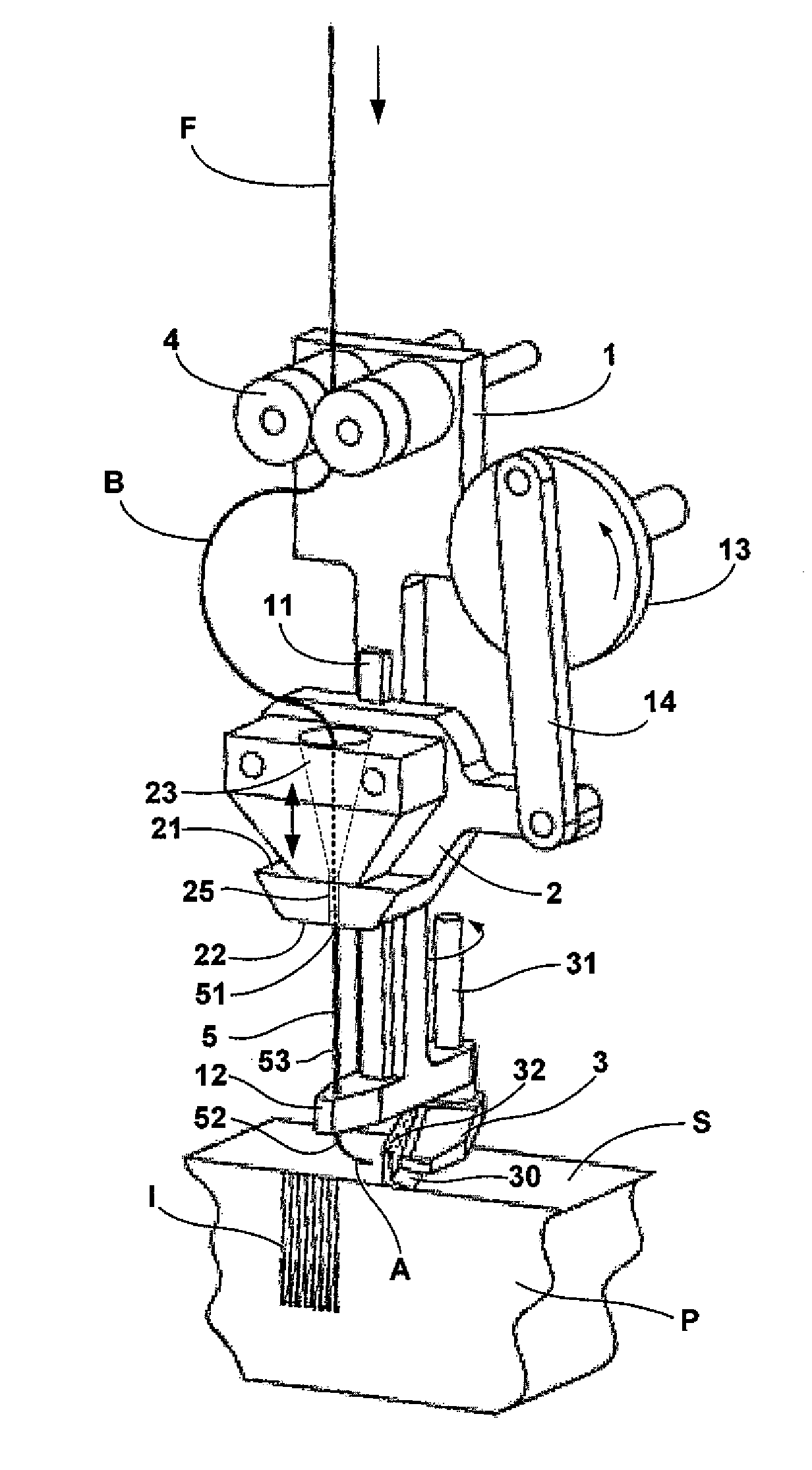
[0041]The device illustrated in FIG. 1 comprises a structure 1 on which are mounted a thread F feed means 4, a moving support 2 supporting a hollow needle 5, and a cutting means 3.

[0042]The feed means 4 is placed at the top of the structure 1 and is able to deliver the thread F at a given and regulated constant speed.

[0043]The moving support 2 is connected to the structure via a straight guide rail 11. This moving support 2 is given a reciprocating movement between a raised position and a lowered position, by a link rod 14 and a crankshaft 13 turned by a motor (not depicted) secured to the structure 1.

[0044]What is meant by the raised position is the position of the structure that corresponds to the phase of the cycle during which the structure is in the position furthest from the surface S of the profiled element P, and the lowered position means the position corresponding to the phase of the cycle during which the structure is in the position closest to the surface S.

[0045]The mov...


PUM

PropertyMeasurementUnit
Diameteraaaaaaaaaa
Lengthaaaaaaaaaa
Distanceaaaaaaaaaa

Abstract

Device for embedding a thread in a rubber profiled element comprising: a continuous thread feeder arranged on a structure, a moving support able to run along the structure between a raised and a lowered position. A hollow needle, comprising a canal in which the thread runs is fixed by one of its ends to the base of the moving support in the duct, and a tip at its other end capable of penetrating the rubber profiled element, a cutter arranged on the structure, comprising a rotary blade able to cut off the thread at a given distance from the tip of the needle upon each cycle of reciprocating movement of the needle. The cutter comprises a paddle arranged behind the cutting wire of the blade and intended to fold the tail around the tip of the needle just after the thread has been cut by the blade.

Description

RELATED APPLICATIONS[0001]This is a U.S. National Phase Application under 35 USC 371 of International Application PCT / EP2010 / 062907, filed on Sep. 2, 2010.[0002]This application claims the priority of French patent application no. 09 / 56009, filed Sep. 3, 2009, the entire content of which is hereby incorporated by reference.FIELD OF THE INVENTION[0003]The invention relates to the technical field of vehicle tyres and, in particular, to that of the manufacture of tyres comprising fibres injected in a given direction into one of the rubber components of which the said tyre is made.BACKGROUND OF THE INVENTION[0004]Publication EP 1 213 130 provides a specific idea of this type of tyre, in which short reinforcing fibres, or inserts, are embedded in the tread in an oriented fashion so as to improve the mechanical properties of this part of the tyre in a given direction.[0005]Publication U.S. Pat. No. 7,005,022 proposes a method for producing this type of component comprising oriented fibres...

Claims


Application Information

Patent Timeline
IPC IPC(8): B29C70/06B29C70/88B60C11/14B29D30/38B29D30/06B29D30/46B29D30/66B29L30/00
CPCB29C70/06B29C70/887B29D30/38B29D30/46B60C11/14B29D30/0678B29D30/66B29L2030/002B29D2030/463B29D2030/662Y10T156/12Y10T156/1052Y10T156/17
Inventor HINC, HENRI
Owner MICHELIN RECH & TECH SA
Why Eureka
Try Eureka