X-ray imaging system for medical use

a technology for medical use and x-ray imaging, applied in the field can solve the problems of increased area, increased size of x-ray image pickup system, time and labor, etc., and achieve the effect of suppressing an increase in area

Active Publication Date: 2015-03-24
HAMAMATSU PHOTONICS KK
View PDF10 Cites 4 Cited by
  • Summary
  • Abstract
  • Description
  • Claims
  • Application Information

AI Technical Summary

Benefits of technology

[0019]In accordance with the present invention, in an X-ray image pickup system for medical use having at least two imaging modes, it is possible to realize the two imaging modes by one solid-state image pickup apparatus and suppress an increase in area required for a photosensitive surface of the solid-state image pickup apparatus.

Problems solved by technology

However, when a plurality of X-ray image pickup apparatuses meeting these requirements are made available, problems that the X-ray image pickup system is increased in size or it is necessary to exchange an X-ray image pickup apparatus at the time of changing an imaging mode, which takes time and labor, are brought about.

Method used


Image

  • X-ray imaging system for medical use
  • X-ray imaging system for medical use
  • X-ray imaging system for medical use

Examples


first embodiment

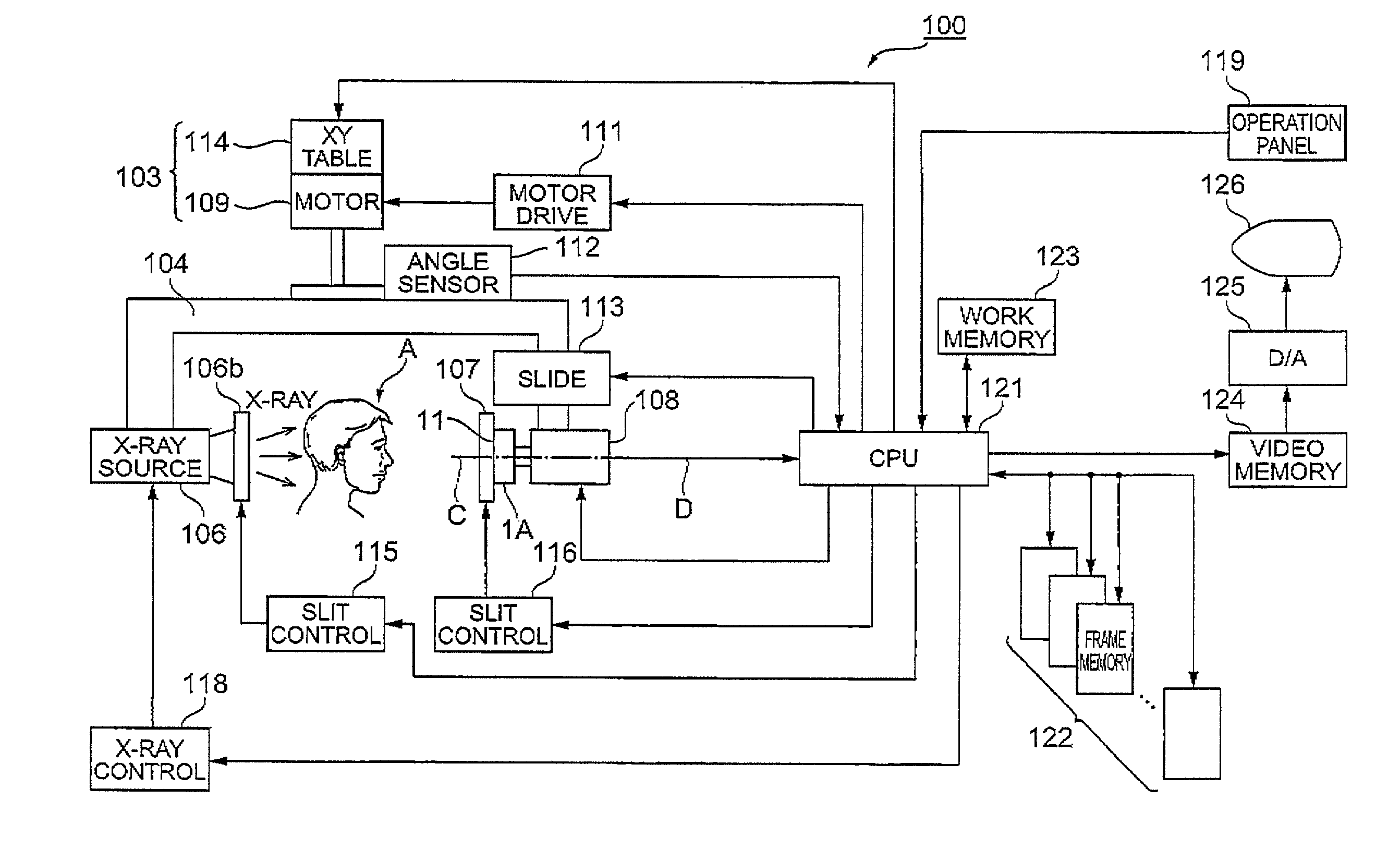
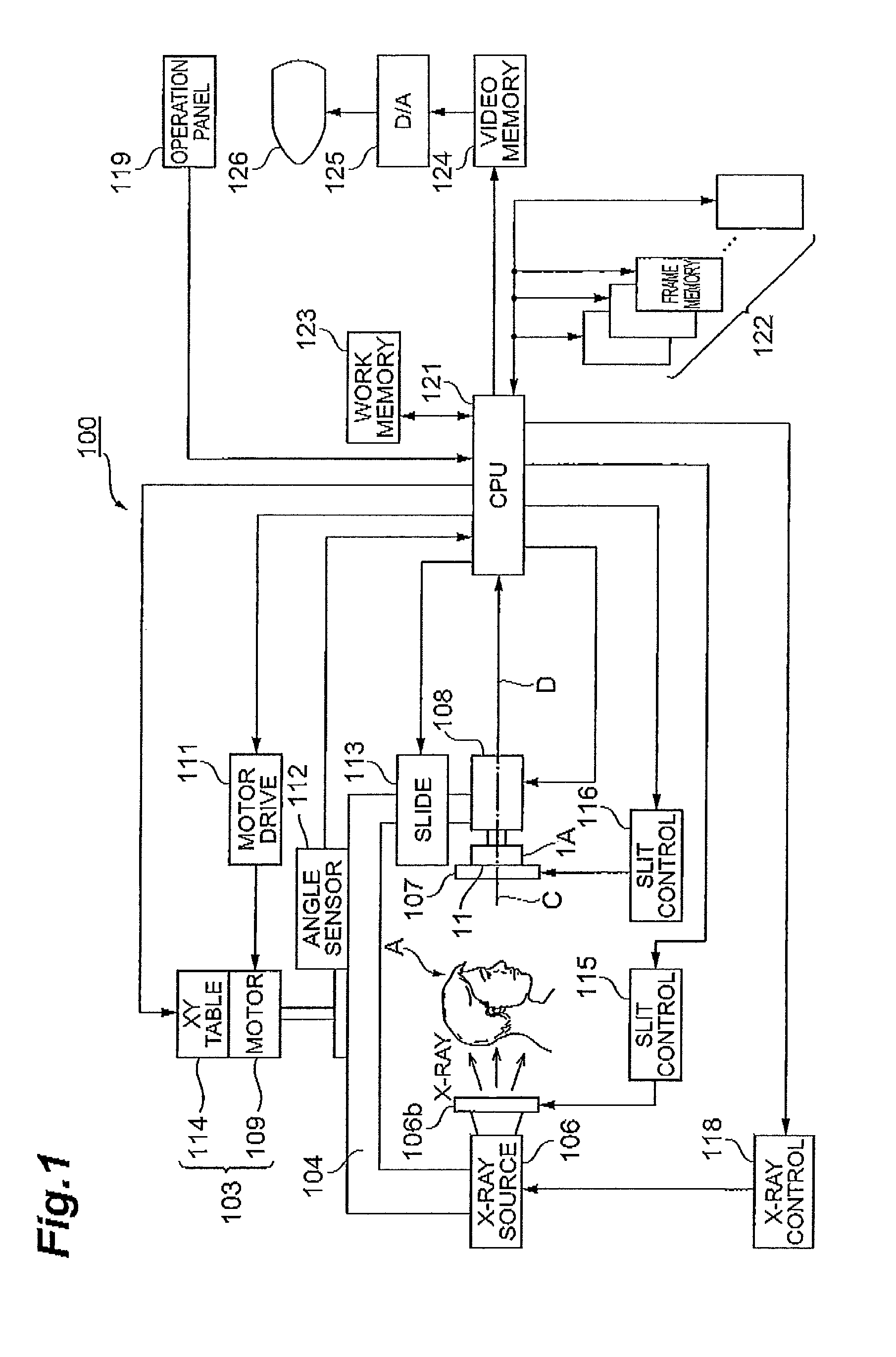
[0039]FIG. 1 is a diagram showing the configuration of an X-ray image pickup system for medical use 100 as the present invention. The X-ray image pickup system 100 of the present embodiment has imaging modes such as panoramic radiography, cephalometrical radiography, and CT scan mainly for dentistry medical treatment, and takes an X-ray image of a jaw portion of a test subject. The X-ray image pickup system 100 is equipped with a solid-state image pickup apparatus and an X-ray generator, and takes an image of an X-ray which is output from the X-ray generator to transmit through a subject A (i.e., a jaw portion of a test subject) by the solid-state image pickup apparatus.

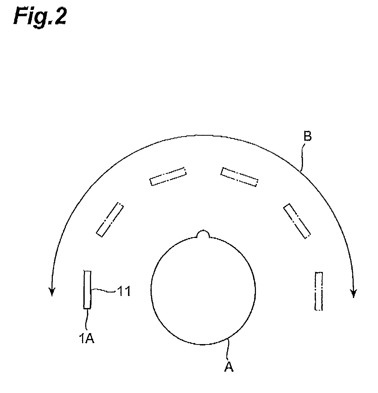
[0040]The X-ray image pickup system 100 shown in this diagram is equipped with a solid-state image pickup apparatus 1A, an X-ray generator 106, and a rotation controlling section 108 supporting the solid-state image pickup apparatus 1A rotatably.

[0041]The X-ray generator 106 generates an X-ray toward the subject A. A...

second embodiment

[0136]The solid-state image pickup apparatus 1B as well has a first imaging mode and a second imaging mode. The imaging areas in the photodetecting section 10B in the first imaging mode and the second imaging mode are different from each other. The controlling section 6B outputs voltage values corresponding to the quantities of charges generated in the respective photodiodes PD of the M×N pixels P1, 1 to PM, N in the photodetecting section 10B from the signal readout section 20 in the first imaging mode. Further, the controlling section 6B outputs voltage values corresponding to the quantities of charges generated in the photodiodes PD of the respective pixels Pm, n in the range from the first row to the M1-th row in the photodetecting section 10B from the signal readout section 20 in the second imaging mode.

[0137]Further, in the second imaging mode, the controlling section 6B reduces a readout pixel pitch in frame data based on a voltage value output from the signal readout sectio...


PUM


Abstract

A solid-state image pickup apparatus 1A is formed such that M×N (where M<N and M and N are integers greater than or equal to 2) pixels are two-dimensionally arrayed in M rows and N columns, and has a photodetecting section 10A having a rectangular photosensitive surface whose longitudinal direction is the row direction. The solid-state image pickup apparatus 1A is supported rotatably by a rotation controlling section, and the rotation controlling section controls a rotation angle of the solid-state image pickup apparatus 1A such that the longitudinal direction of the photodetecting section 10A is made parallel to a moving direction B of the solid-state image pickup apparatus 1A in one imaging mode of the two imaging modes, and the longitudinal direction of the photodetecting section 10A is made perpendicular to the moving direction B of the solid-state image pickup apparatus 1A in the other imaging mode of the two imaging modes.

Description

TECHNICAL FIELD[0001]The present invention relates to an X-ray image pickup system for medical use.BACKGROUND ART[0002]In X-ray photography for medical use, in recent years, an X-ray imaging system using an X-ray image pickup apparatus in place of an X-ray sensitive film has been extensively used. Such an X-ray imaging system does not require development like that for an X-ray sensitive film, and is highly convenient in the point that it is possible to confirm an X-ray image in real time or the like, that also has superior points in aspects of data storage quality and data handling facilitation. In X-ray photography for dental diagnosis, also, such an X-ray imaging system has been used in various types of imaging modes, such as panoramic radiography, cephalometrical radiography, and CT scan.[0003]In the case of a dental X-ray image pickup system, in some cases, the shape of an imaging area required for an X-ray image pickup apparatus differs according to various types of imaging mod...

Claims


Application Information

Patent Timeline
Patent Type & Authority Patents(United States)
IPC IPC(8): H04N7/18A61B6/00A61B6/03A61B6/14G01T1/20G01T1/29H04N5/225H04N5/32H04N5/321H04N5/369H04N5/374H04N5/378
CPCA61B6/032A61B6/14A61B6/4233G01T1/2928H04N5/2259H04N5/32H04N5/374H04N5/378A61B6/03A61B6/4441H04N23/58H04N25/76H04N25/75
Inventor MORI, HARUMICHIKYUSHIMA, RYUJIFUJITA, KAZUKI
Owner HAMAMATSU PHOTONICS KK
Why Eureka
Try Eureka