
Instrument and method for detecting partial electrical discharges

a technology of partial electrical discharge and instrument, which is applied in the direction of instruments, electric devices, transportation and packaging, etc., can solve the problems of loss of information, unreliable or insignificant measurement data, and information essential for subsequent processing of signals for diagnostic purposes

Inactive Publication Date: 2015-03-24
TECHIMP TECHNOLOGIES SA
View PDF18 Cites 4 Cited by
  • Summary
  • Abstract
  • Description
  • Claims
  • Application Information

AI Technical Summary

Benefits of technology

The aim of this invention is to provide a tool and technique for detecting partial electric discharges that are straightforward and highly sensitive, with the added benefit of being resilient to noise and offering maximum flexibility in processing and analyzing the data collected. This helps improve the accuracy and sensitivity of measurement using a simple device while still being able to work with and analyze the data collected.

Problems solved by technology

As to the difficulties of interpreting the results of partial discharge measurements, these depend on the fact that the measured data may be unreliable or insignificant.
In effect, during detection of the signals associated with the partial discharges, information essential for subsequent processing of the signals themselves for diagnostic purposes may be lost (loss of information might consist, for example, of failure to detect a pulse or failure to detect the waveform of a pulse).
It should be noted, however, that the signals detected are current pulses which are correlated with load transfers that occur in the defects in the electrical apparatus being checked and constitute the partial discharges, but they do not constitute a direct measurement of the load transfers.
Accordingly, the standard states that instruments with a particularly wide detection bandwidth (greater than a few MHz) cannot be calibrated in compliance with the standard.
In other cases, two instruments in parallel or in series are used, one broadband and one narrowband, but without the possibility of comparing the results in compliance with the standard and with evident waste of time and resources.
The latter solution, too, is not free of disadvantages, however.
In effect, a digital filter of that kind is complex to make and also requires expensive components.
Another problem in measuring partial discharges lies in the fact that the signals detected do not always correspond to the partial discharges but often include components corresponding to noise.
In particular, the measuring circuit often includes signal components relating to common mode noise (consisting of homopolar components) due to noise which couples to the measuring circuit through earth.
These methods may be quite effective but have the disadvantage of requiring considerable resources in terms of computation capacity and time.
These instruments make it possible to eliminate certain types of disturbances but have the disadvantage of not allowing detected signals to be processed for the purposes of extracting parameters other than the pulse amplitude and the pulse phase relative to the supply voltage.
That means there is the risk of discharge pulses with a very high frequency content not being detected at all by the system.
Thus, the instrument is not very reliable for diagnostic purposes.

Method used


Image

  • Instrument and method for detecting partial electrical discharges
  • Instrument and method for detecting partial electrical discharges
  • Instrument and method for detecting partial electrical discharges

Examples


Embodiment Construction

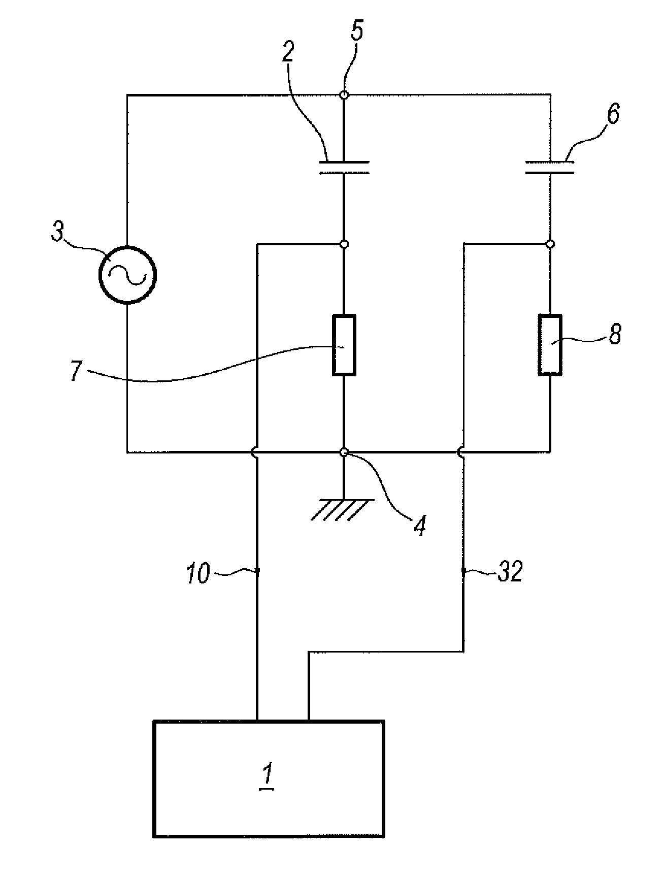
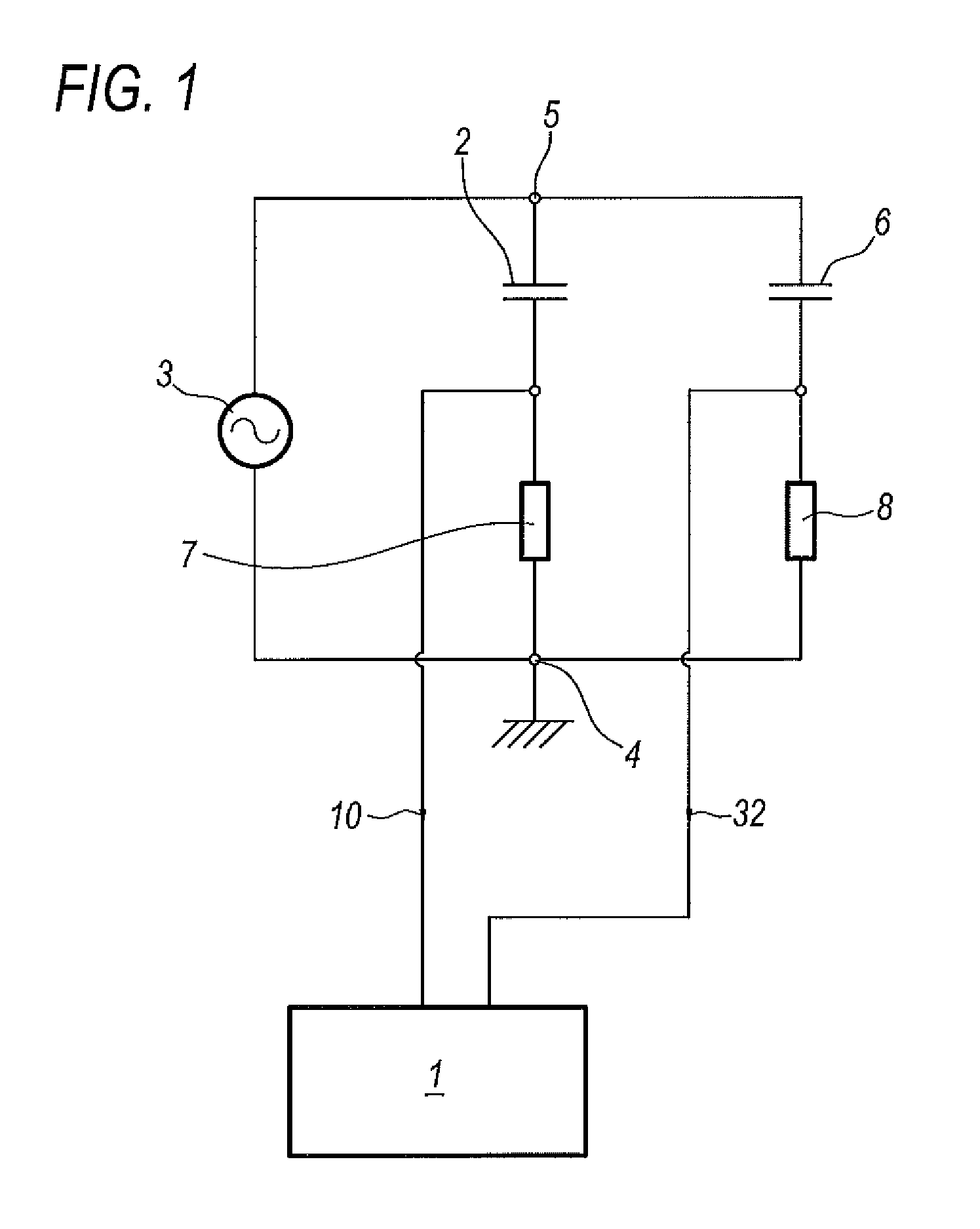
[0061]The numeral 1 in the accompanying drawings denotes an instrument for detecting partial electric discharges in an electric apparatus.

[0062]The electric apparatus to be measured is schematically represented in FIG. 1 as a capacitor 2.

[0063]The electric apparatus 2 to be measured is connected across a power source 3, designed to apply high voltage to the electric apparatus 2, and an earth node 4.

[0064]Connected in parallel to the apparatus 2, across a high-voltage node 5 and the earth node, there is a capacitor 6 constituting a form of capacitance known as coupling capacitance.

[0065]The coupling capacitor 6, together with the measuring apparatus 2, forms a mesh for looping the partial discharge signals in order to form a partial discharge measuring circuit.

[0066]The measuring circuit also comprises a measuring impedance device 7 connected across a low-voltage terminal of the apparatus 2 and the earth, node 4, this measuring impedance device 7 being hereinafter referred to as dire...


PUM


Abstract

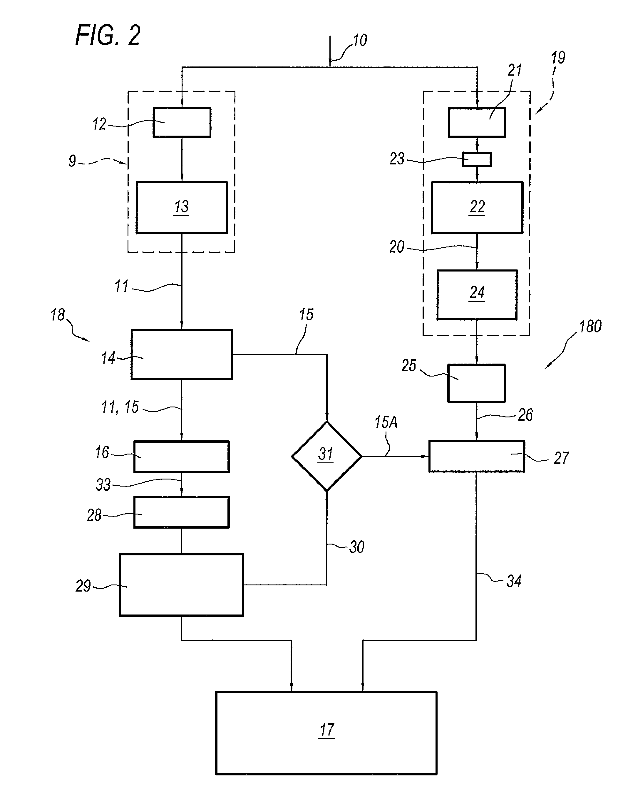
An instrument (1) and a method for detecting partial electric discharges involve acquiring a discharge signal (10), for example picked up by a direct-measuring impedance device (7) through a broadband HF acquisition channel (18), and acquiring the discharge signal (10) in a narrowband LF acquisition channel (180) complying with regulations, using on the LF acquisition channel (180) a trigger controlled in slave mode by a trigger of the broadband HF acquisition channel (18); they also involve acquiring another discharge signal (32) picked up by an indirect-measuring impedance device (8) through a second narrowband LF acquisition channel (180A) and comparing digital signals (34, 34A) generated in the first and second LF acquisition channels (180, 180A), in order to generate a balanced digital signal (36) without components representative of common mode electrical signals present in the measuring circuit.

Description

TECHNICAL FIELD[0001]This invention relates to an instrument and a method for detecting partial electrical discharges.[0002]It should be noted that a partial discharge is an electric discharge limited to a portion of the insulation of an electrical apparatus and does not therefore cause immediate failure of the apparatus but its gradual degradation. By their very nature, therefore, partial discharges are substantially limited in extent to a defect in the insulating system. In light of this, diagnostic methods based on the detection and interpretation of partial discharges are among the most promising and widely studied in the context of scientific research since the study of partial discharges makes it possible to investigate the nature of defects in the insulating system where the discharges occur.[0003]The detection and processing of partial discharges for diagnostic purposes, however, has not yet become a standard industrial tool for planning the maintenance and / or substitution o...

Claims


Application Information

Patent Timeline
Patent Type & Authority Patents(United States)
IPC IPC(8): G01R31/00G01R21/00G01R31/12
CPCG01R31/1227G01R31/12
Inventor SERRA, STEFANOMONTANARI, GIAN CARLOBETTIO, FABIANO
Owner TECHIMP TECHNOLOGIES SA
Learn More