Movable EMF shield, method for facilitating rapid imaging and treatment of patient

a technology of magnetic resonance imaging and shield, which is applied in the field of magnetic resonance imaging (mri) and linear accelerator (linac) technologies, can solve the problems of linac not being able to house in the same room, wreak havoc with mri image quality, artifacts and aberrations in mri images,

Active Publication Date: 2015-03-31
UCHICAGO ARGONNE LLC +1
View PDF14 Cites 36 Cited by
  • Summary
  • Abstract
  • Description
  • Claims
  • Application Information

AI Technical Summary

Benefits of technology

[0012]Another object of the invention is to provide a compact MRI / LINAC enclosure. A feature of the enclosure is the imposition of movable EMI shields between imaging and treating equipment. An advantage of the enclosure is that radiation treatment is enabled within 30-45 seconds after imaging of the patient has determined the situs of the tumor to be irradiated.

Problems solved by technology

MRI has drawbacks related to non-invasive treatment scenarios.
Ubiquitous electromagnetic radiation can cause artifacts and aberrations in MRI images.
Unfortunately, every electronic device (including radiation treatment machines such as LINACs) emanates extraneous electromagnetic radiation (EMR), which while harmless to humans, wreaks havoc with MRI image quality.
The problem becomes how an MRI imaged patient can be then quickly shuttled from the MRI enclosure to an area (albeit awash in EMR) for treatment by a LINAC or other electronic device.
The LINAC cannot be housed in the same room as the MRI due to the LINAC emitting electromagnetic radiation.
But, the organs in the body continually shift such that targeting and irradiating internal structures becomes problematic even just a few minutes after imaging.

Method used


Image

  • Movable EMF shield, method for facilitating rapid imaging and treatment of patient
  • Movable EMF shield, method for facilitating rapid imaging and treatment of patient
  • Movable EMF shield, method for facilitating rapid imaging and treatment of patient

Examples


example 1

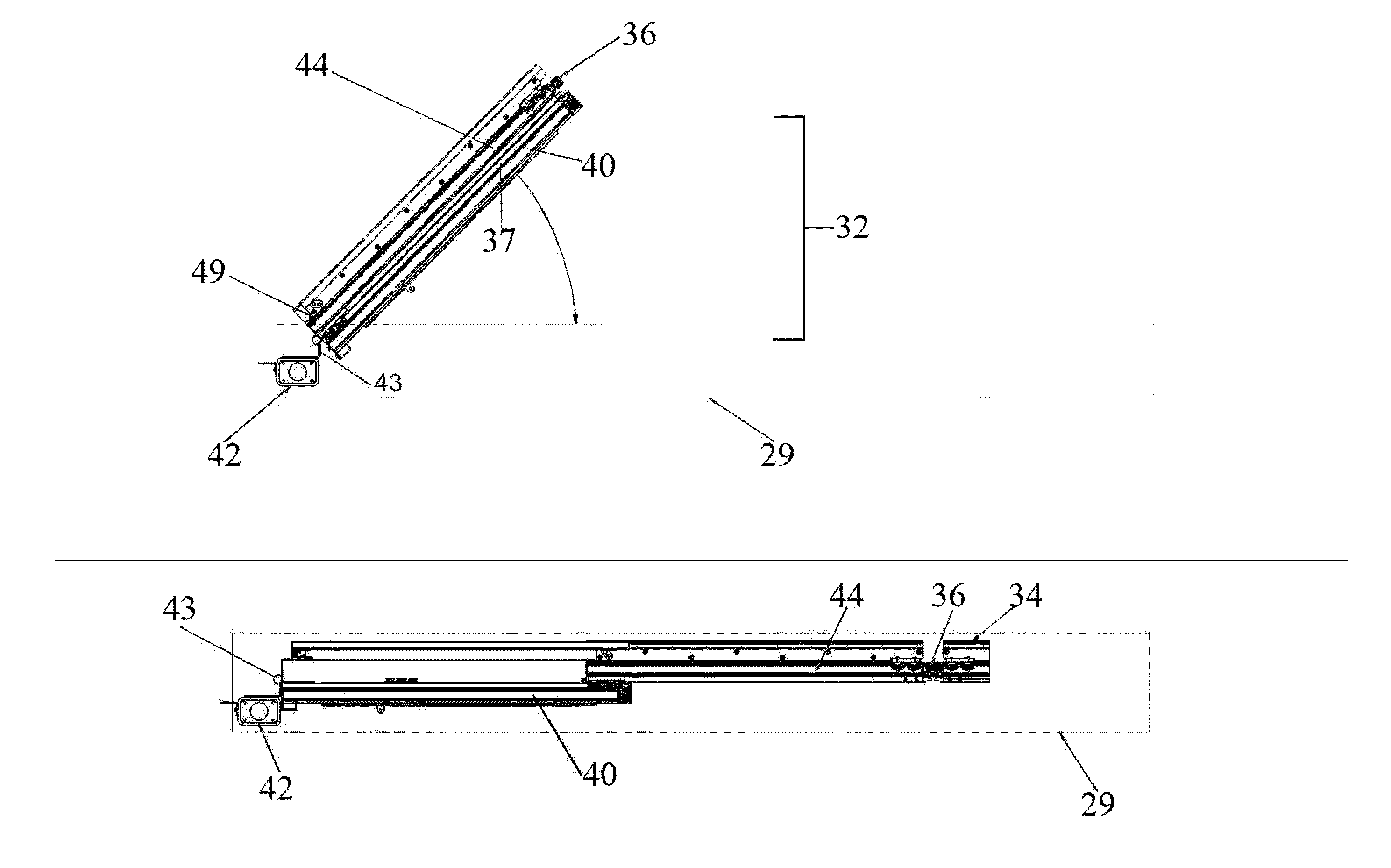
[0069]In an embodiment of the movable emf shield, a sliding door (second panel 44) connects to the swing door (first panel 40) via two engagement rails 53 which are mounted on the upper and lower medially facing surface 45 of the sliding door. In an embodiment of the invention, the sliding door (panel 44) is always connected to the swing door (first panel 40) even when the swing door is not underneath the header 29. The swing door has corresponding roller bearings 51 that are positioned to be received by the rails when the swinging door panel is positioned within the track 29.

[0070]The header tracks (i.e., those tracks superiorly positioned relative to other tracks on the swinging door) are notched to allow the sliding door roller bearing to engage / disengage from the header. A rail cover on the header track prevents the sliding door from accidently disengaging from the track once the sliding door starts moving in a distal direction to engage with the opposing sliding door from the o...


PUM


Abstract

A radio frequency shield which reversibly transects an electromagnetic frequency enclosure is provided. The shield includes first a number of panels attached to a first surface of the enclosure. The panels are adapted to move through a first arc relative to the first surface. Shield also includes a first panel from the number of panels having a first leading edge capable of transecting the first arc. The shield further includes a second number of panels attached to a second surface of the enclosure. The second set of panels is adapted to move through an arc relative to the second surface of the enclosure. Also a second panel from said second set of panels has a second leading edge capable of transecting the second arc so as to oppose the first leading edge. Finally, the shield includes a means for reversibly attaching the first leading edge to the second leading edge while simultaneously establishing electrical communication between the first and second plurality of panels.

Description

PRIORITY[0001]This U.S. Utility Patent Application claims the benefits of U.S. Provisional Patent Application No. 61 / 664,276 filed on Jun. 26, 2012.BACKGROUND OF THE INVENTION[0002]1. Field of the Invention[0003]The present invention relates to Magnetic Resonance Imaging (MRI) and Linear Accelerator (LINAC) technologies, and more specifically, the present invention relates to a system for stowing and deploying MRI and LINAC equipment within the same enclosure for rapid patient imaging and treatment.[0004]2. Background of the Invention[0005]MRI is the de facto standard for soft tissue imaging. It allows physicians to know precisely the location of injury, tumor growth, and organ malfunction. This aids surgeons in pinpointing situs of entry into the body. It also facilitates non-invasive treatment, such as radiation therapy.[0006]MRI has drawbacks related to non-invasive treatment scenarios. Structures (organs, tumors, fluids) within the body move, sometimes shifting by as much as an ...

Claims


Application Information

Patent Timeline
Patent Type & Authority Patents(United States)
IPC IPC(8): H01R4/00A61B5/00A61B5/055A61N5/10G01R33/422G01R33/48H05K9/00
CPCH05K9/0003G01R33/422A61B5/0046G01R33/4808A61B5/055A61N2005/1055
Inventor WEIBLER, JOSEPH CORZECHOWSKI, THOMAS WKILGORE, STEVEN THAMOUZ, MICHAEL G
Owner UCHICAGO ARGONNE LLC
Why Eureka
Try Eureka