Magnetic resonance imaging

a magnetic resonance imaging and imaging sequence technology, applied in the field of magnetic resonance imaging, can solve the problems of reduced image artifacts, inability to provide adequate fast scan times, and inability to meet the requirements of mri imaging sequences and techniques, so as to improve the signal-to-noise ratio, increase the efficiency of the magnetic resonance imaging device, and improve the effect of signal-to-noise ratio

Active Publication Date: 2007-06-12
FONAR
View PDF8 Cites 21 Cited by
  • Summary
  • Abstract
  • Description
  • Claims
  • Application Information

AI Technical Summary

Benefits of technology

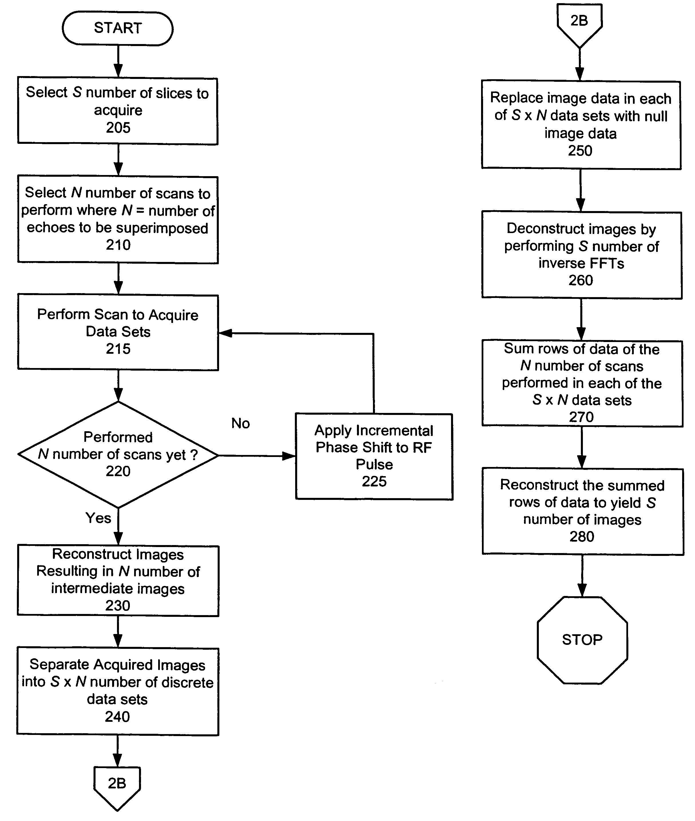
[0021]The present invention provides a method and apparatus to increase the efficiency of a Magnetic Resonance Imaging (MRI) device by utilizing a multi-slice fast magnetic resonance imaging scan and advancing the phase of the radio frequency excitation with each warp level to correct artifacts and improve the signal-to-noise ratio. Image data from the scans is manipulated, and inverse Fourier transforms are performed to render images with increased signal-to-noise and full spectrum frequency response in a reduced acquisition time.
[0022]Through advancing the phase of the radio frequency (RF) excitation with each phase-encoding level, the present invention increases the effectiveness of an MRI device by correcting for main magnetic field inhomogeneities without noticeably decreasing the signal-to-noise ratio. The present invention also increases the effectiveness of fast imaging with steady precession (FISP) scans and allows FISP scans to image multiple slices. In an MRI device, a patient is subjected to a constant magnetic field, and RF pulses are used to excite the nuclei in the patient's body. The nuclei release a corresponding RF signal as the nuclei r

Problems solved by technology

Steady state free precession techniques often permit fast imaging with high signal-to-noise ratios, but they are susceptible to image artifacts due to inhomogeneities in the main B0 m

Method used


Image

  • Magnetic resonance imaging
  • Magnetic resonance imaging
  • Magnetic resonance imaging

Examples


Embodiment Construction

[0030]The following detailed description is presented to enable any person skilled in the art to make and use the invention. For purposes of explanation, specific nomenclature is set forth to provide a thorough understanding of the present invention. However, it will be apparent to one skilled in the art that these specific details are not required to practice the invention. Descriptions of specific applications are provided only as representative examples. Various modifications to the preferred embodiments will be readily apparent to one skilled in the art, and the general principles defined herein may be applied to other embodiments and applications without departing from the scope of the invention. The present invention is not intended to be limited to the embodiments shown, but is to be accorded the widest possible scope consistent with the principles and features disclosed herein.

[0031]The present invention is a Magnetic Resonance Imaging (MRI) method and apparatus that collect...


PUM


Abstract

Through advancing the phase of radio frequency (RF) excitation with each phase-encoding level, a method and apparatus increases the effectiveness of a Magnetic Resonance Imaging (MRI) device by correcting for main magnetic field inhomogeneities without noticeably decreasing the signal-to-noise ratio. The present invention also increases the effectiveness of fast imaging with steady precession (FISP) scans and allows FISP scans to image multiple slices. In an MRI device, a patient is subjected to a constant magnetic field, and RF pulses are used to excite the nuclei in the patient's body. The nuclei release a corresponding RF signal as the nuclei relax, which can be measured and mapped into a visual display. The RF pulses used to excite the nuclei in the body cooperate with a slice select gradient and a phase-encoding gradient. When the RF pulse is phase shifted with each phase-encoding gradient level, improved signal-to-noise ratios are observed.

Description

TECHNICAL FIELD[0001]The technical field generally relates to magnetic resonance imaging. More specifically, the invention relates to a method for improving the efficiency of a magnetic resonance imaging apparatus by utilizing a multi-slice fast magnetic resonance imaging sequence and advancing the phase of the radio frequency excitation with each warp level to correct artifacts and improve the signal-to-noise ratio of the resulting images.BACKGROUND[0002]Magnetic resonance imaging (MRI), also called nuclear magnetic resonance imaging (NMR imaging), is a non-invasive method for the analysis of materials and is used extensively in medical imaging. It is non-destructive and does not use ionizing radiation. In general terms, nuclear magnetic moments of nuclei in the imaged material are excited at specific spin precession frequencies, which are proportional to an external magnetic field. Radio frequency (RF) signals resulting from the precession of these spins are collected using receiv...

Claims


Application Information

Patent Timeline
IPC IPC(8): G01V3/00
CPCG01R33/4835G01R33/5613G01R33/56563G01R33/5608
Inventor MORRONE, TERRY
Owner FONAR
Why Eureka
Try Eureka