Circuit arrangement for switching a current, and method for operating a semiconductor circuit breaker

a circuit arrangement and current switching technology, applied in the direction of electronic switching, oscillator generator, pulse technique, etc., can solve the problems of high switching loss in the power semiconductor, damage to the components of the semiconductor circuit breaker b>26/b>, etc., to prevent the adverse influence of the switching behavior of the circuit arrangemen

Active Publication Date: 2015-03-31
SIEMENS AG
View PDF13 Cites 8 Cited by
  • Summary
  • Abstract
  • Description
  • Claims
  • Application Information

AI Technical Summary

Benefits of technology

[0030]In a further advantageous development of the inventive circuit arrangement, the actuation device is so designed as to receive a digital signal via a switching input using a fault-tolerant transmission protocol and/or to send a ...

Problems solved by technology

Consequently, components of the semiconductor circuit breaker 26 may be damaged.
One disadvantage of such a solution is that the switching ...

Method used


Image

  • Circuit arrangement for switching a current, and method for operating a semiconductor circuit breaker
  • Circuit arrangement for switching a current, and method for operating a semiconductor circuit breaker
  • Circuit arrangement for switching a current, and method for operating a semiconductor circuit breaker

Examples


Embodiment Construction

[0038]The examples represent preferred embodiments of the invention.

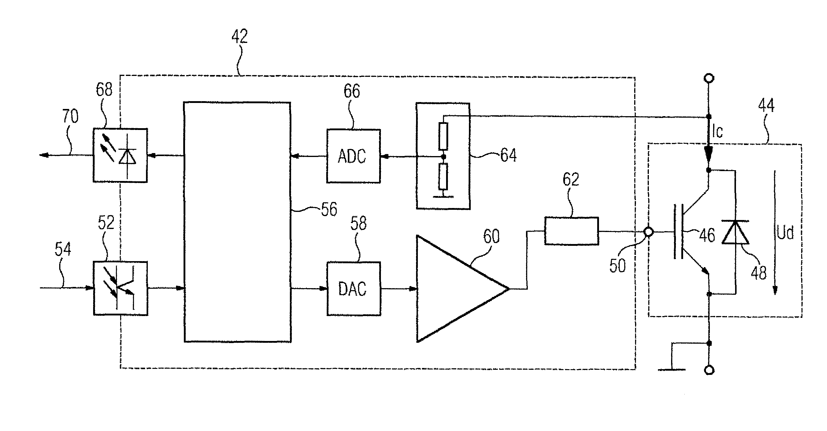
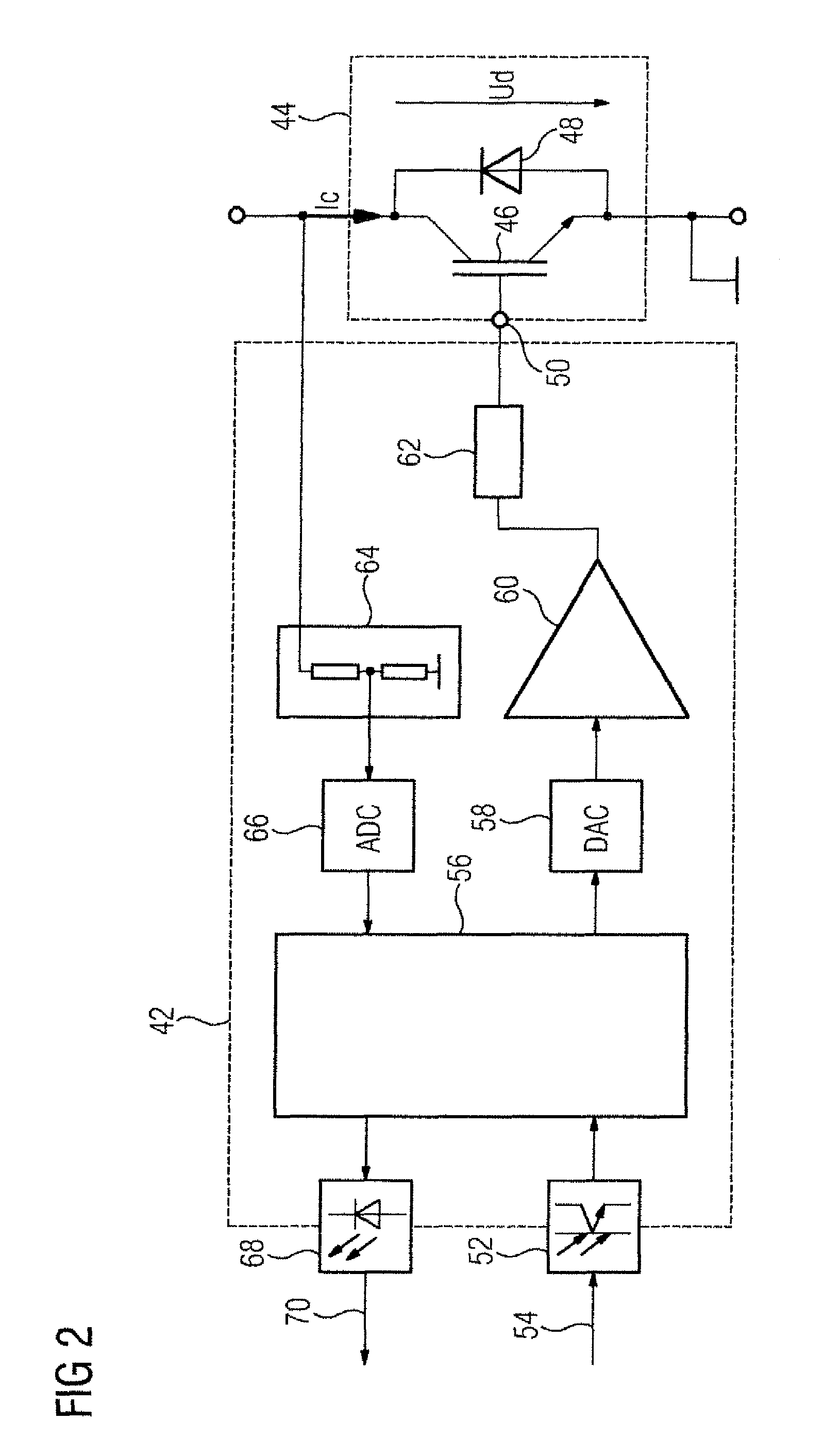
[0039]FIG. 2 shows an actuation circuit 42 which is integrated into a controlled converter (not shown in further detail in FIG. 2) of a frequency converter. A structural design of the converter can correspond to that of the converter 10. The actuation circuit 42 controls a semiconductor circuit breaker 44. This has a transistor 46 (here an IGBT) and a diode 48 which is antiparallel connected to the transistor 46. A MOSFET, for example, can also be provided instead of the IGBT. In order to control the semiconductor circuit breaker 44, the actuation circuit 42 generates a control voltage at a control input 50 of the semiconductor circuit breaker 44. The control input 50 here corresponds to the gate of the IGBT 46. The actuation circuit 42 and the semiconductor circuit breaker 44 together represent an embodiment of the inventive circuit arrangement. A current Ic is controlled by means of the semiconductor circuit break...


PUM


Abstract

A control voltage is generated at a control input of a semiconductor circuit breaker by an actuation circuit at switching flanks of a switching signal, said control voltage having a profile which is flattened in relation to the profile of the switching signal. With the disclosed method, the switching losses in a semiconductor circuit breaker are reduced. By defining a value for a switching parameter of a control device of the actuation circuit, the switching behavior of the actuation circuit can be influenced by the switching parameter. A specific parameter value of the switching parameter can be varied during operation of the actuation circuit.

Description

CROSS-REFERENCES TO RELATED APPLICATIONS[0001]This application is the U.S. National Stage of International Application No. PCT / EP2012 / 063648, filed Jul. 12, 2012, which designated the United States and has been published as International Publication No. WO 2013 / 010898 and which claims the priority of German Patent Application, Serial No. 10 2011 079 552.9, filed Jul. 21, 2011, pursuant to 35 U.S.C. 119(a)-(d).BACKGROUND OF THE INVENTION[0002]The invention relates to a circuit arrangement for switching a current as a function of a predefined switching signal. The circuit arrangement comprises a semiconductor circuit breaker for switching a current and an actuation device for the semiconductor circuit breaker. The actuation device is so designed as to receive the switching signal and to generate a control voltage at a control input of the semiconductor circuit breaker as a function of the received switching signal.[0003]A circuit arrangement of this type is disclosed in WO 2008 / 032113...

Claims


Application Information

Patent Timeline
IPC IPC(8): H03K17/14H03K17/082
CPCH03K17/14H03K17/0828
Inventor GEDIGA, SWENHANDT, KARSTENSOMMER, RAINER
Owner SIEMENS AG
Why Eureka
Try Eureka