Case packing system having robotic pick and place mechanism and dual dump bins

a case and robot technology, applied in the field of robot case packing system, can solve the problems of affecting the range of movement of multi-axis robots, affecting the quality of packaging materials,

Active Publication Date: 2015-04-07
FALLAS DAVID M
View PDF111 Cites 95 Cited by
  • Summary
  • Abstract
  • Description
  • Claims
  • Application Information

AI Technical Summary

Benefits of technology

[0008]A robotic case packing system loads articles from a moving conveyor system into containers. A robotic pick and place mechanism is disposed above the articles conveyed on an article conveyor and is disposed in between first and second rotatable (i.e., pivoting or tiltable) bins situated next to the article conveyor. A controller operates the system and moves the pick and place mechanism in three axes in two sets of picking movements. In first picking movements, the mechanism picks and places the articles from the conveyor into the first bin while the first bin is in its set or upright position. Once the first bin is full, the controller rotates (i.e., pivots or tilts) the first bin from the set position, to a pivoted position, and then back to the set position. When pivoted, the bin allows the articles stacked in the first bin to slip into a container held below the first bin on a case conveyor. In this way, the stacked articles stand up in the open container, which can be later closed and sealed.
[0009]After completing the first picking movements, the mechanism picks and places the articles from the conveyor into the second bin in second picking movements. Once the second bin is full, the controller rotates (i.e., pivots or tilts) the second bin from the set position, to a pivoted position, and then back to the set position to fill another container on the case conveyor with the stacked articles. To speed up handling, the controller pivots the first bin during the second picking movements used to fill the second bin. Likewise, the controller pivots the second bin during the first picking movements used to fill the first bin.
[0010]The first and second bins can pivot about an axis parallel to or perpendicular to the conveyance direction of the conveyed articles, and each of the bins can have a flap or lid actuated to squeeze or compress the product to eliminate any slippage of the product while pivoting the bins to load the container. Once the bins are fully pivoted, then the flap or lid can be relaxed to allow the product to be loaded into the container. In this way, the articles can slip out an open side of the bin. The flap or lid can also squeeze or compress the articles in the bin, which can help the articles to better fit standing up in the container.
[0011]To coordinate handling, the controller can use sensors for sensing passage of the articles on the article conveyor and can control the speed of the article conveyor. Additionally, the controller can control the position of the containers on the case conveyor and can use actuatable stops and other mechanisms to properly position the containers below the bins.

Problems solved by technology

While this multiplicity of heads increases the packing speed, the means for moving the robot heads from the conveyor system to the container may be awkward or cumbersome to implement.
Many such multi-axis robots, however, have proven to be fairly slow and heavy.
Additionally, it has been found that with some three-axis robots, the range of movement may be limited in certain directions.
For example, certain three-axis robots are very limited in their vertical component, which can make movement of an article from a conveyor into a deep container difficult to perform.

Method used


Image

  • Case packing system having robotic pick and place mechanism and dual dump bins
  • Case packing system having robotic pick and place mechanism and dual dump bins
  • Case packing system having robotic pick and place mechanism and dual dump bins

Examples


Embodiment Construction

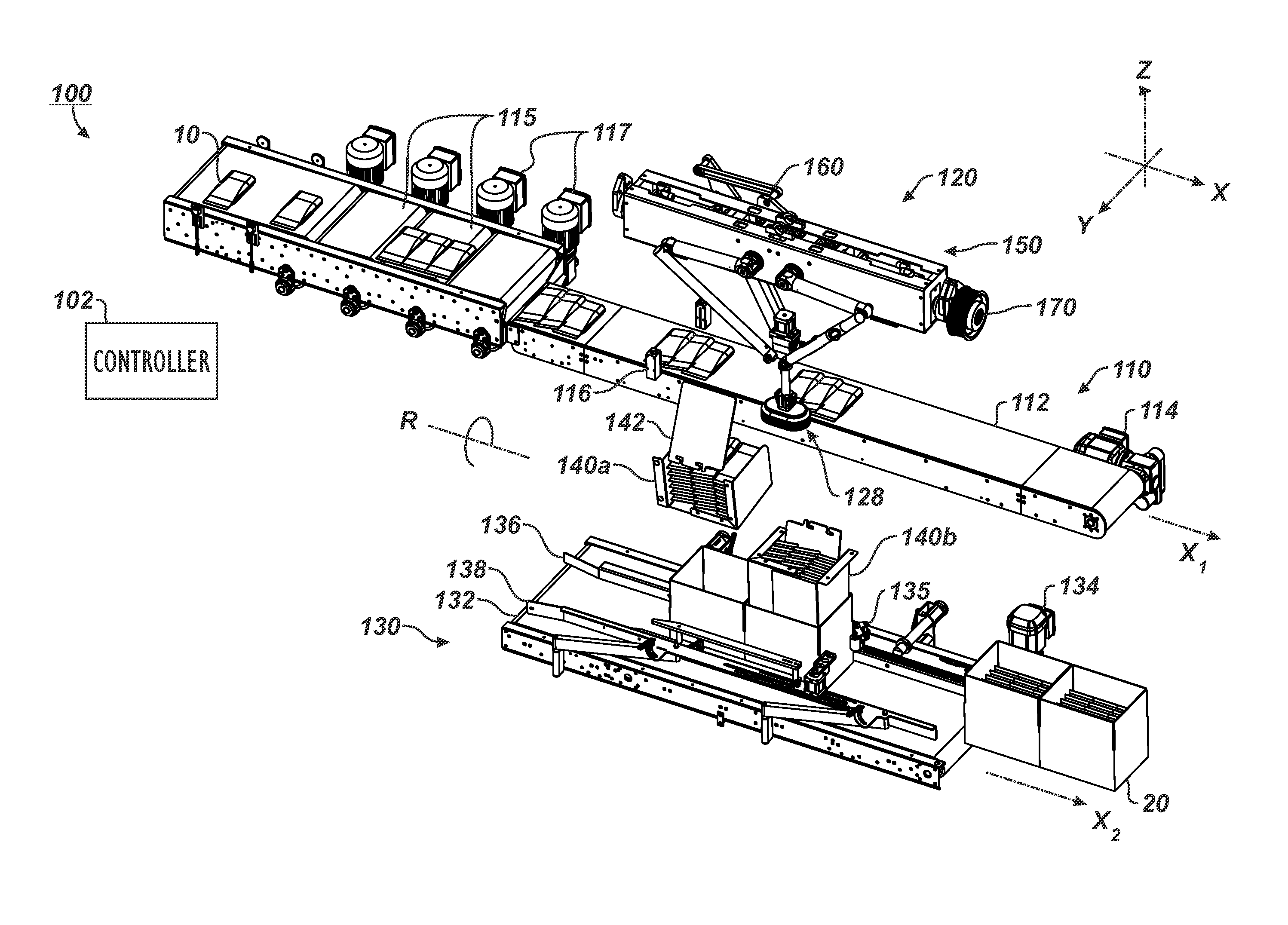
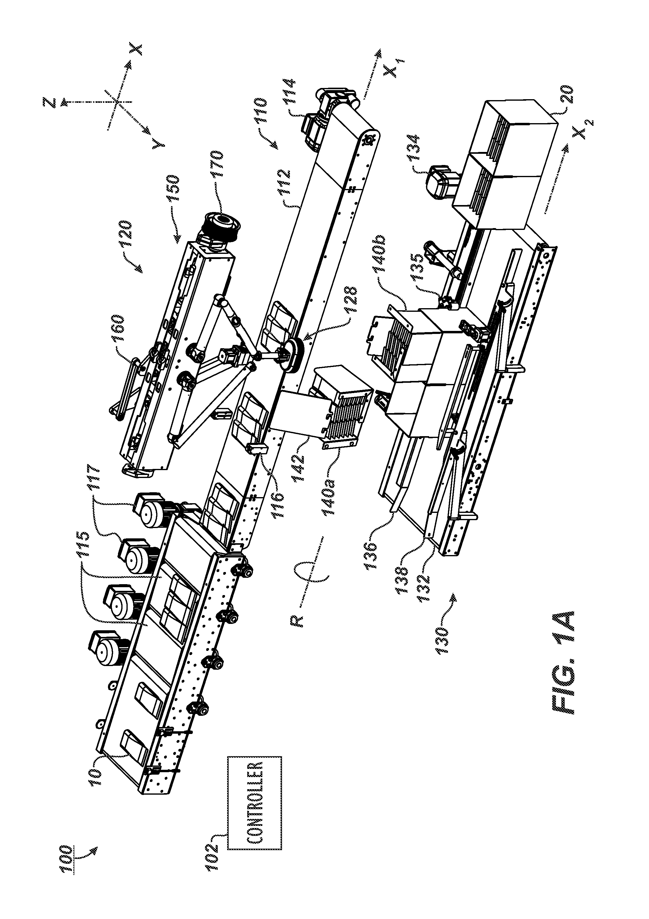
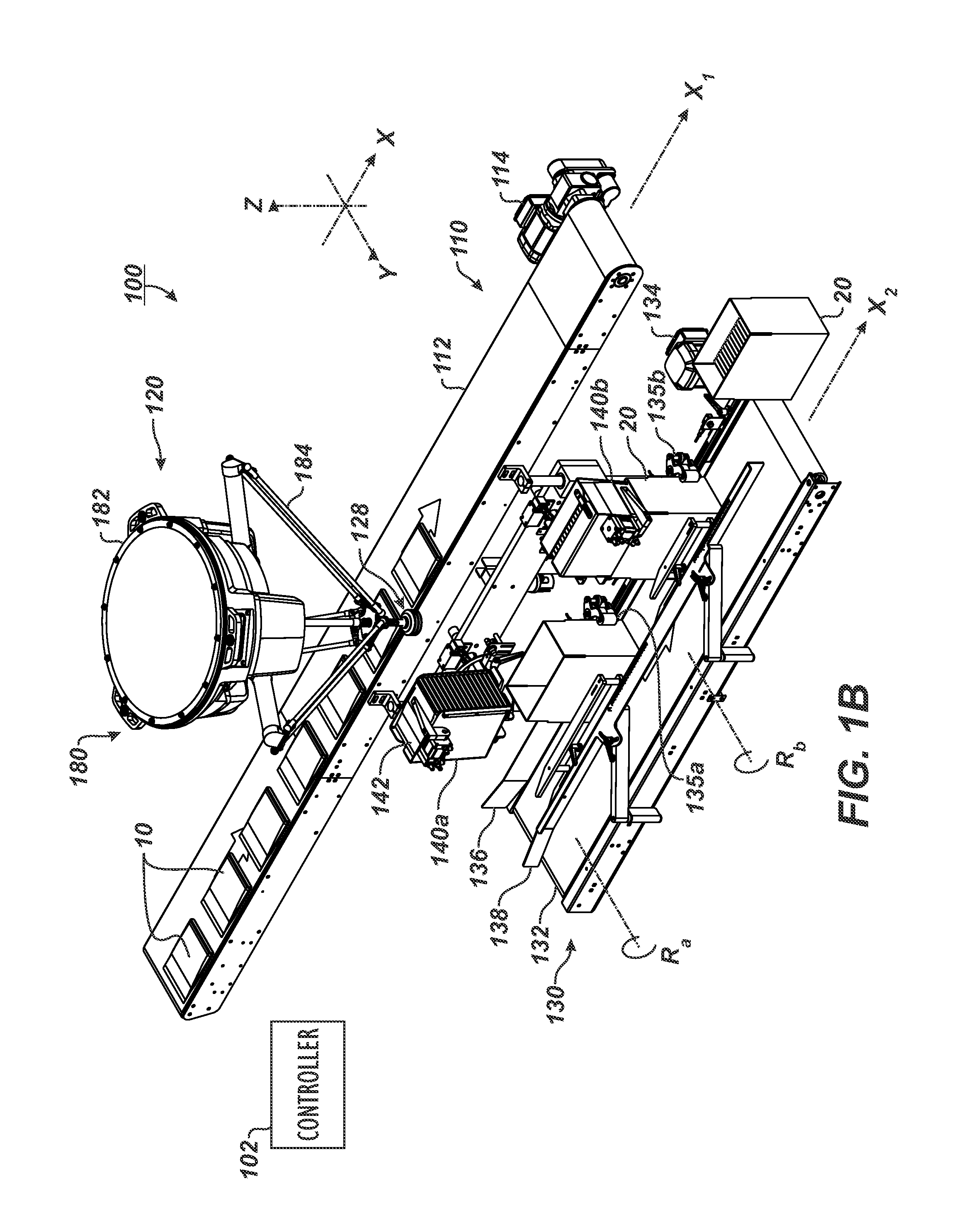
[0021]Referring to FIG. 1A-1B, a robotic case packing system 100 according to the present disclosure includes an article conveyor 110, a case conveyor 130, a control system 102 (shown schematically), and a pick and place mechanism 120. The robotic case packing system 100 uses the pick and place mechanism 120 to alternatingly pick articles 10 from the article conveyor 110 with a handler 128 and stack the picked article(s) 10 into one of two dump bins 140a-b. In turn, the system 100 rotates (i.e., pivots or tilts) the dump bins 140a-b to place the articles 10 into containers 20 (e.g., boxes) moved in position on the case conveyor 130 below. The articles 10 can be packages, bags, boxes, or any other type of item or product that can be loaded onto the article conveyor 110.

[0022]In FIG. 1A, the pick and place mechanism 120 uses a multi-axis robotic device 150 having a two-axis robot 160 and a pivot 170 to move the handler 128 in three axes (X, Y, Z) similar to the multi-axis robot disclo...


PUM

PropertyMeasurementUnit
speedaaaaaaaaaa
packing speedaaaaaaaaaa
flexibilityaaaaaaaaaa

Abstract

A robotic case packing system loads articles from one conveyor into containers on another conveyor using a robotic pick and place mechanism and a set of pivoting bins. A controller moves the robotic mechanism in first picking movements to pick and place articles from the conveyor into the first bin. Once the first bin is full, the controller pivots the first bin to allow the articles stacked in the first bin to be loaded into a container held below. While the first bin is pivoting, the controller moves the robotic mechanism to pick and place articles from the conveyor into the second bin. The process repeats with the controller pivoting the second bin during the picking movements used to fill the first bin and vice versa.

Description

BACKGROUND OF THE DISCLOSURE[0001]1. Field of the Disclosure[0002]The present disclosure relates to a case packing system and, more particularly, to a robotic case packing system for loading articles from a moving conveyor into containers, such as corrugated cardboard boxes.[0003]2. Description of Related Art[0004]For many years, attempts have been made to develop improved systems for picking up individual articles from a conveyor or similar conveyor system and depositing those articles within a container, such as a corrugated cardboard box. The desire is to accomplish this task with speed and accuracy. To meet the demand for speed, past solutions have used multiple robots along the conveyor, such as described in Applicant's U.S. Pat. No. 6,540,063, which is incorporated herein by reference. Often, if four such robot heads are used, each head picks up every fourth article on the conveyor system in a staggered manner so that the four robot heads effectively remove four consecutive ar...

Claims


Application Information

Patent Timeline
Patent Type & Authority Patents(United States)
IPC IPC(8): B65B5/08B65G47/30
CPCB65G47/30B65B5/08B65G47/914B25J9/0051B25J9/0093B25J9/107B65B35/50B65B35/56
Inventor FALLAS, DAVID M.
Owner FALLAS DAVID M
Why Eureka
Try Eureka