Load-n-go platform lift systems

a platform lift and platform technology, applied in the field of cargo loading, can solve the problems of own set of hazards, less than ideal, and time-consuming for the trailer hookup process

Inactive Publication Date: 2015-04-07
LEARNED JAMES
View PDF17 Cites 6 Cited by
  • Summary
  • Abstract
  • Description
  • Claims
  • Application Information

AI Technical Summary

Benefits of technology

[0011]In view of the foregoing disadvantages inherent in the known cargo loading art, the present invention provides a novel cargo self-loading and hauling system. The general purpose of the present invention, which will be described subsequently in greater detail, is to provide safety and speed in loading, transporting, and unloading various equipment and cargos.
[0014]The cargo platform system may be independently powered using a power feed source which may be a 110 or 220 volt alternating voltage circuit or the system may be powered from the vehicle's 12 volt system as well in alternate embodiments. The first jack, the second jack, the third jack, and the fourth jack each comprise electric motors (may be master / slave) and are in communication together such that extendable or retractable operation is simultaneous between the first jack, the second jack, the third jack, and the fourth jack in the jack system. The perimeter frame further comprises mounts for the four jacks, which are affixed to the left front corner, the right front corner, the left rear corner, and the right rear corner respectively. The jacks at the left front corner and the right front are mounted either on a telescoping / sliding mounting system or may be mounted on a pivoting bracket mounting system such that the left front jack and the right front jack can be positioned so that they will not interfere with the removal of the hauling truck from underneath the loading platform. The simultaneous operation of the jacks allows the platform to be loaded and unloaded in a substantially level condition such that the vehicle is not stressed by such operations. In this way the present invention doesn't cause the vehicle's rear end to ‘squat’ and the front end to be raised, but rather loads the vehicle in a balanced fashion. This promotes longevity of the host vehicle and doesn't endanger the load by tilting it at an angle.
[0015]The jacks may be slideably removable from the perimeter of the platform and each jack is cylindrical in shape with the bottom of each jack level with the bottom of the platform and the top of each jack extending upward. Each jack is about 4 feet in height when in a retracted position and is each about 7 feet in height when in an extended position. The jack system is able to lower the platform into close proximity to a ground surface such that a ramp system may not be necessary to load heavy cargo. However, some low ground clearance vehicles / cargo may require short ramps 36″ or less to facilitate loading / unloading. These ramps are easily stowable between the platform and the sub-frame. A hinged tailgate may also double as a load / unload ramp. The rear edge of the platform may also be dropped or angled to form an integral ramp in the platform itself. Each jack in the system may comprise feet on the bottom surface of the extendable portion of each jack such that the jacks will not readily sink into a soft ground surface. Hard wheeled casters could be used at the bottom of the jack legs so that the platform could be rolled about on a hard surface.
[0016]The sub-frame preferably comprises mud flaps, brake lights, tail lights, turn signals, and backup lights in communication with the vehicle's operator controls and when the sub-frame is mounted onto the vehicle, the vehicle conforms to legal highway requirements without the platform mounted onto the sub-frame. The deck-rails comprise guide-locks for the platform-rails to be contact guided into a parallel planar relation to the deck-rails and the platform-rails are able to be coupled together with the guide-rails via the guide-locks using aligning orifices in the platform-rails. The sub-frame is designed such that it does not require alterations to the vehicle, and provides added strength to the vehicle's frame structure.

Problems solved by technology

The cargo bed on a pickup is able to haul a considerable amount of cargo of varying shapes, but is less than ideal when the bed interior has less than a 4 foot unobstructed surface.
Towing and backing a trailer requires added skills that the average car driver doesn't possess, and the time required for the trailer hookup process can be considerable as well.
Commercial applications may need to situate cargo and / or equipment at locations that could be very difficult if not virtually impossible to back a trailer into.
In addition, the second vehicle's own propulsion system is used to move the weight of the second vehicle up the ramp and onto the bed, which creates its own set of hazards.
Other cargos that are not self-propelled, such as tool boxes, generators, air compressors, may be wheeled, but may be very difficult to load by use of readily-available ramp systems.
Many fatalities, injuries, and accidents using loading ramps are reported annually.
Common factors contributing to accidents using ramps are: improperly securing the ramps; movement of the first vehicle during the loading process; improper spacing of the ramps; improper rating of the ramps; reduced capacity of ramps due to damage; and ramps being too short for the height of the deck being loaded which may cause the motorcycle or other vehicle to become high-centered.
Ramps for such purposes are usually also carried by the small vehicle and take up cargo space, being long and bulky in shape.
Perfect carrying and securing methods for the ramps are not always found because the shape and size of the cargo to be hauled is not always known and the ramps must be loaded onto the first vehicle after the cargo is already in position.

Method used


Image

  • Load-n-go platform lift systems
  • Load-n-go platform lift systems
  • Load-n-go platform lift systems

Examples


Embodiment Construction

[0029]As discussed above, embodiments of the present invention relate to a cargo loading device and more particularly to a cargo loading and hauling system as used to improve safety, speed of loading and unloading, and to reduce labor.

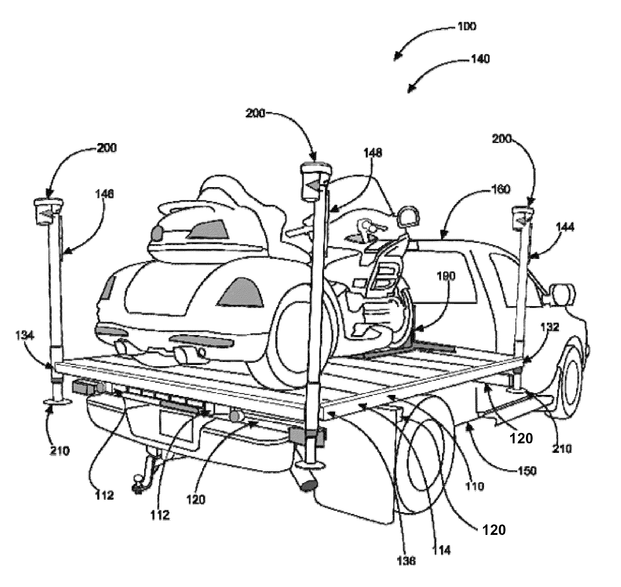
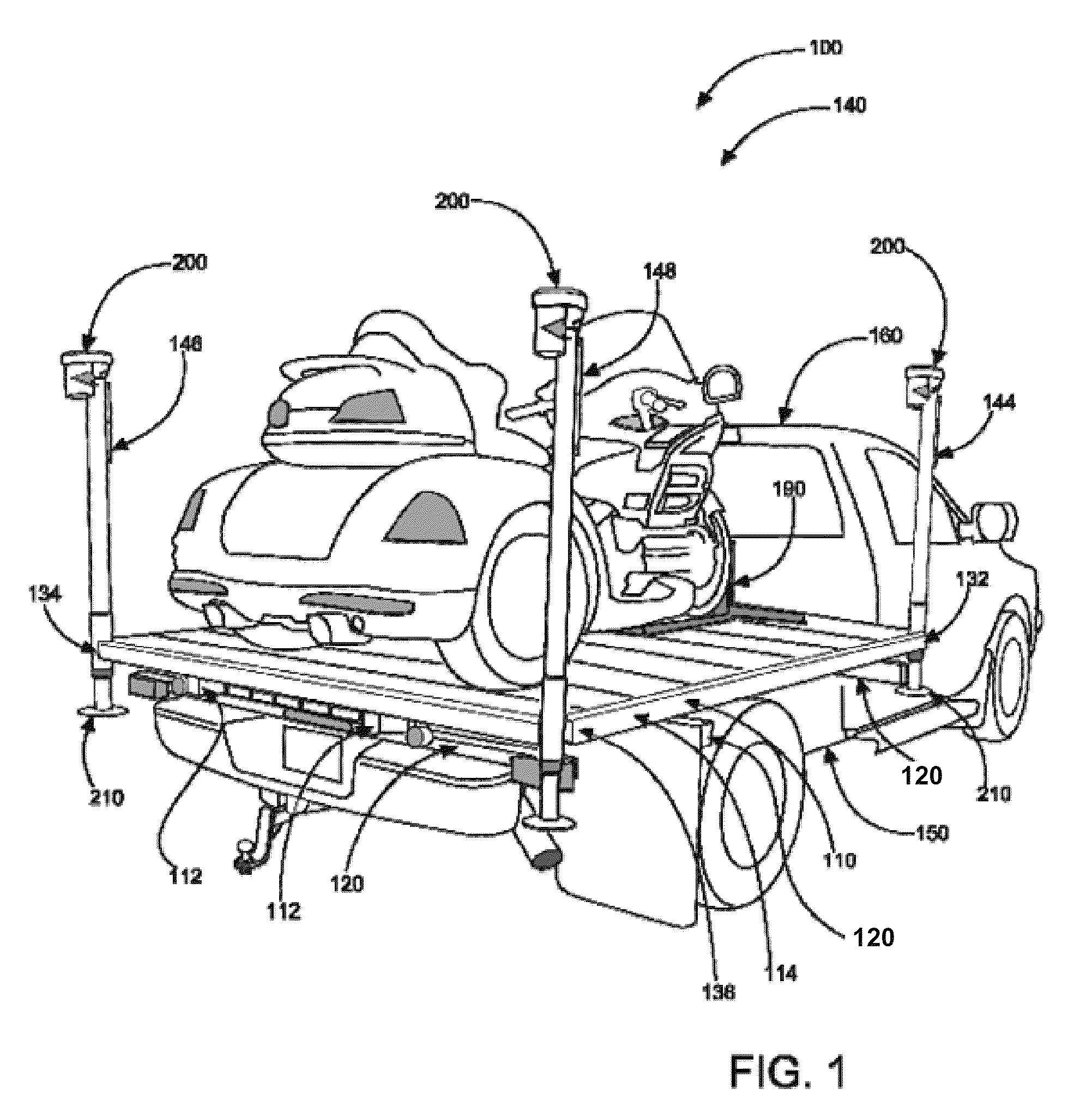
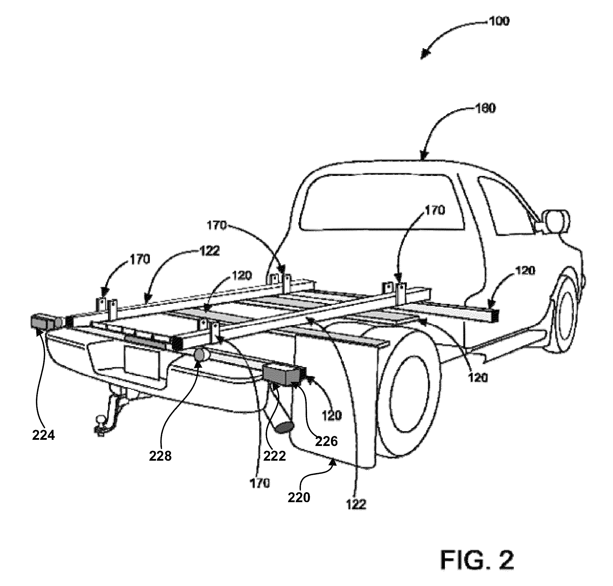
[0030]Referring to the drawings by numerals of reference there is shown in FIG. 1, shows a perspective view illustrating cargo platform system 100 according to an embodiment of the present invention. Cargo platform system 100 of the present invention comprises platform 110 that is self-contained, designed to allow one person to independently pick up and transport excessively heavy (or light) loads. Cargo platform system 100 is designed to allow individuals to pick up and transport loads effectively eliminating the need for long, heavy ramps or other equipment. Cargo platform system 100 may comprise: a sub-frame 120 having deck-rails 122; platform 110 (having platform rails 112; perimeter frame 114 having left front corner 130, right front corner 132, l...


PUM


Abstract

A cargo platform system which can be uncoupled from a vehicle frame and lowered to a ground surface using a self-contained jack system after the vehicle has been removed from beneath the platform. The cargo platform system may comprise a sub-frame having deck-rails for attachment to a vehicle frame, a platform having deck-rails for removably coupling to the sub-frame, and a jack system comprising a first jack, a second jack, a third jack, and a fourth jack removably attached to a left front corner, a right front corner, a left rear corner, and a right rear corner respectively. All four jacks of the jack system are in communication together such that extension and retraction of the jacks are simultaneous and electric motors atop each jack are removable for storage.

Description

CROSS-REFERENCE TO RELATED APPLICATION[0001]The present application is related to and claims priority from prior provisional application Ser. No. 61 / 435,506, filed Jan. 24, 2011 which application is incorporated herein by reference.COPYRIGHT NOTICE[0002]A portion of the disclosure of this patent document contains material which is subject to copyright protection. The copyright owner has no objection to the facsimile reproduction by anyone of the patent document or the patent disclosure, as it appears in the Patent and Trademark Office patent file or records, but otherwise reserves all copyright rights whatsoever. 37 CFR 1.71(d).BACKGROUND OF THE INVENTION[0003]The following includes information that may be useful in understanding the present invention(s). It is not an admission that any of the information provided herein is prior art, or material, to the presently described or claimed inventions, or that any publication or document that is specifically or implicitly referenced is pr...

Claims


Application Information

Patent Timeline
Patent Type & Authority Patents(United States)
IPC IPC(8): B60P1/64
CPCB60P1/6445
Inventor LEARNED, JAMES
Owner LEARNED JAMES
Why Eureka
Try Eureka