Vehicle speed control system

Inactive Publication Date: 2017-03-02
TOYOTA JIDOSHA KK
View PDF0 Cites 8 Cited by
  • Summary
  • Abstract
  • Description
  • Claims
  • Application Information

AI Technical Summary

Benefits of technology

[0022]In the system as described above, when the lower one of the first maximum speed and the second maximum speed exceeds the speed limit, the vehicle is controlled such that the speed at the start position of the curve becomes substantially equal to the speed limit. Namely, when the lower one exceeds the speed limit, the vehicle is controlled, under control of the control unit, such that the speed of the vehicle is not only kept from being controlled to the lower one, but the speed of the vehicle is more positively controlled to the speed limit. Thus, in ei

Problems solved by technology

However, according to the related art as described above, a speed limit for the road on which the vehicle is traveling is not taken into c

Method used


Image

  • Vehicle speed control system
  • Vehicle speed control system
  • Vehicle speed control system

Examples


first embodiment

[0037]In the following, a vehicle speed control system according to a first embodiment of the invention will be described with reference to FIG. 1 through FIG. 5.

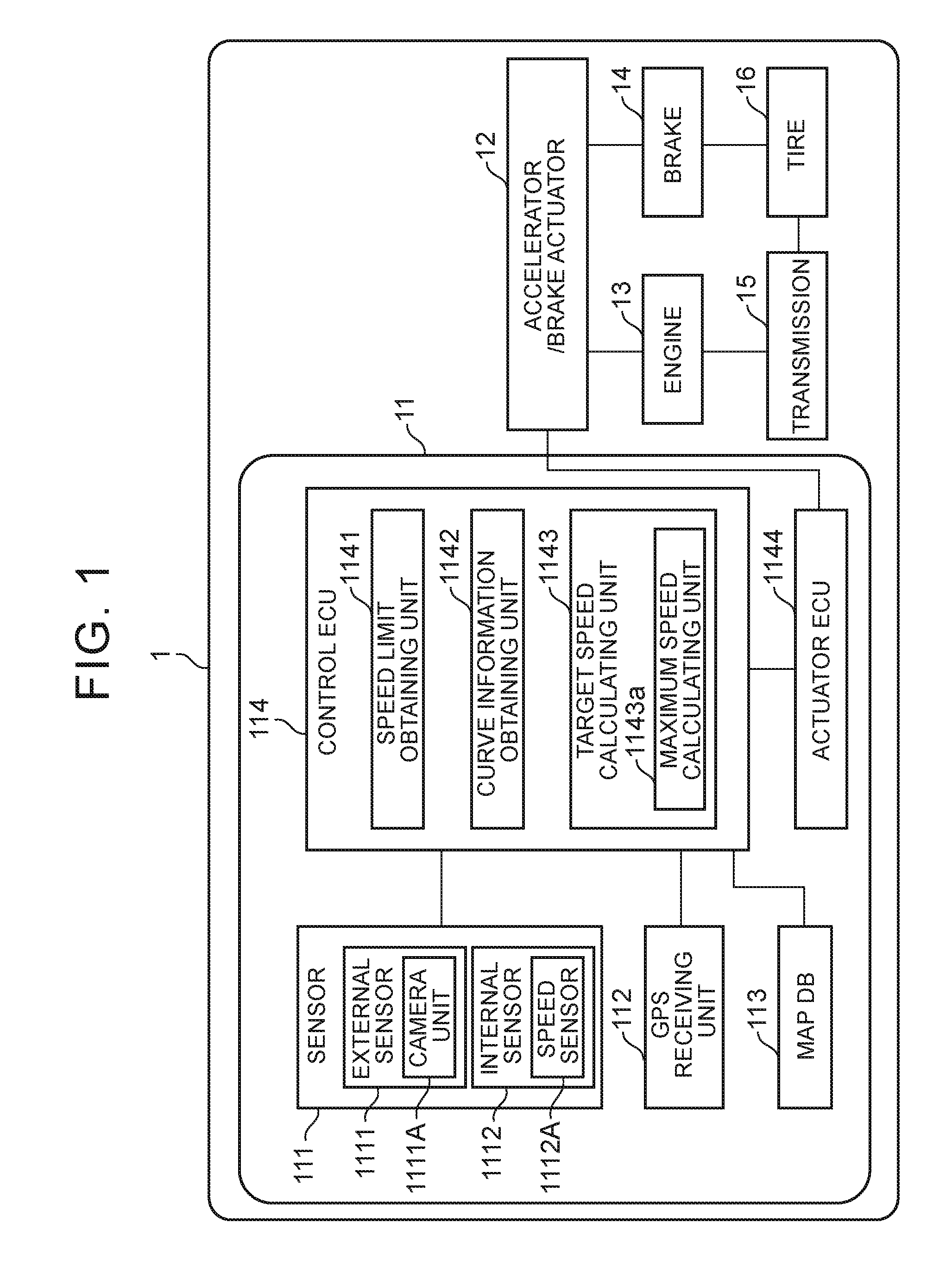
[0038]Referring to FIG. 1, one example of the vehicle speed control system of the first embodiment will be described. FIG. 1 is a block diagram showing one example of the configuration of a vehicle on which the vehicle speed control system of the first embodiment is installed.

[0039]As shown in FIG. 1, the vehicle 1 includes the vehicle speed control system 11, accelerator / brake actuator 12, engine 13, brake 14, transmission 15, and tires 16.

[0040]In order to calculate various signals to be output to the accelerator / brake actuator 12, the vehicle speed control system 11 includes sensors 111, GPS (Global Positioning System) receiving unit 112, map DB (database) 113, control ECU (Electronic Control Unit) 114, and an actuator ECU 1144.

[0041]The sensors 111 are detection devices for detecting information necessary or useful for ...

second embodiment

[0083]Referring next to FIG. 6 through FIG. 8, a vehicle speed control system according to a second embodiment of the invention will be described. While a part of the operation is different between the second embodiment and the first embodiment as described above, there are many similar or common portions in the remaining part of the operation. Therefore, only a portion of the second embodiment which is different from that of the first embodiment as already described above will be described in detail, and description of overlapping portions will be omitted as appropriate.

[0084]One example of the vehicle speed control system of the second embodiment will be described. FIG. 6 is a block diagram showing one example of the configuration of a vehicle on which the vehicle speed control system of the second embodiment is installed.

[0085]The vehicle speed control system 21 according to the second embodiment shown in FIG. 6 is installed on the vehicle 2, and is different from that of the fir...


PUM


Abstract

A vehicle speed control system includes a speed limit obtaining unit that obtains a speed limit for a road in front of a vehicle, a curve information obtaining unit that detects a curve on the road, and calculates a distance from a current position of the vehicle to a start position of the curve and a radius of curvature of the curve, a calculating unit that calculates a first maximum speed at which the vehicle does not deviate from a traveling lane on the curve, based on the radius of curvature, and a control unit that controls the vehicle such that a speed of the vehicle at the start position becomes substantially equal to the first maximum speed, when the first maximum speed does not exceed the speed limit.

Description

INCORPORATION BY REFERENCE[0001]The disclosure of Japanese Patent Application No. 2015-166068 filed on Aug. 25, 2015 including the specification, drawings and abstract is incorporated herein by reference in its entirety.BACKGROUND OF THE INVENTION[0002]1. Field of the Invention[0003]The invention relates to a system that performs driving support when a vehicle travels along a curve, for example, and in particular to a system that controls the vehicle speed before the vehicle enters the curve.[0004]2. Description of Related Art[0005]As one example of this type of system, a system has been proposed which obtains information on a radius of curvature of a curve, calculates a permissible speed at which the vehicle is permitted to travel along the curve, from the radius of curvature, and gives warning to a vehicle driver when the speed of the vehicle exceeds the permissible speed (see Japanese Patent Application Publication No. 07-266919 (JP 07-266919 A)).[0006]However, according to the r...

Claims


Application Information

Patent Timeline
IPC IPC(8): B60K31/00B60W30/14B60W40/072
CPCB60K31/0066B60W40/072B60W30/146B60W2720/106B60W2550/146B60W2420/42B60W2550/22B60W2720/10B60W2552/30B60W2555/60B60W30/143
Inventor OIKAWA, YOSHITAKATANAKA, SHINMORALES TERAOKA, EDGAR YOSHIO
Owner TOYOTA JIDOSHA KK
Why Eureka
Try Eureka