
Grouting method for anchoring with polymer

a polymer and anchor rod technology, applied in the direction of anchoring bolts, earthwork drilling and mining, mining structures, etc., can solve the problems of high cost, inconvenient transportation and storage, and complex processing of water-contained cement volume,

Active Publication Date: 2015-04-14
WANG FUMING
View PDF8 Cites 4 Cited by
  • Summary
  • Abstract
  • Description
  • Claims
  • Application Information

AI Technical Summary

Benefits of technology

[0008]The present invention provides a method for rapid, safe, lightweight and high strength polymer grouting according to development requirements of foundation, tunnel and side slope supporting anchorage and deficiencies of a conventional anchoring technology in China. By taking advantage of the present invention, an anchoring material and a rod body are well consolidated with a rock and soil mass around, the present invention provided a safe, advanced, economic and practical new method for foundation pit, tunnel, side slope supporting, and especially for collapsible loess not suitable for utilizing cement grout as a anchor rod material and a soil expanding with water.
[0009]In view of the above, an object of the present invention is to provide:
[0010]a grouting method for anchoring with polymer, comprising steps of:
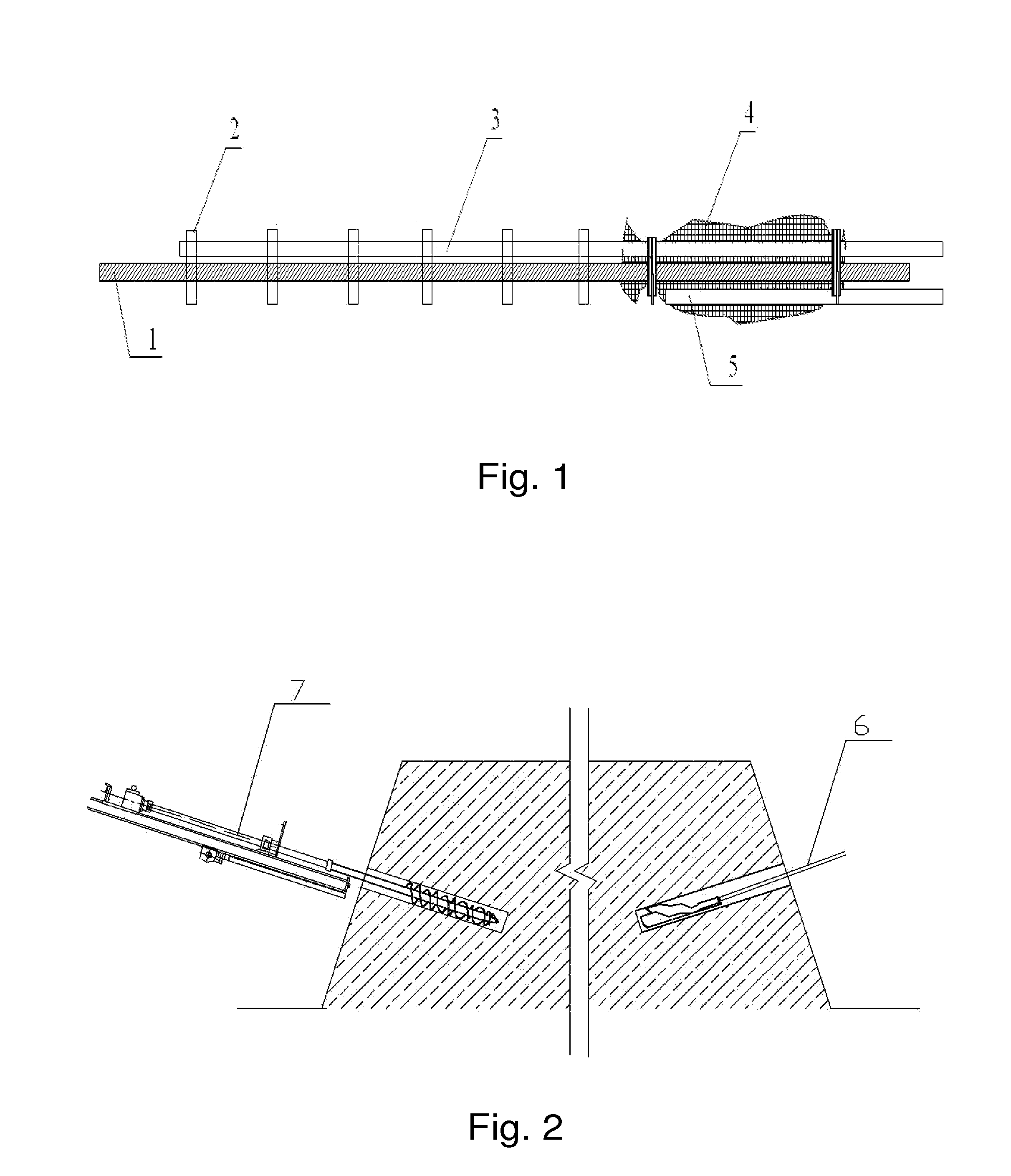
[0011]a) processing a rod body, wherein the rod body is straightened, derusted and preserved at first, and then raw materials are cut, holders are welded and centring holders are provided every 0.5 m˜2 m on the rod body according to design requirements;
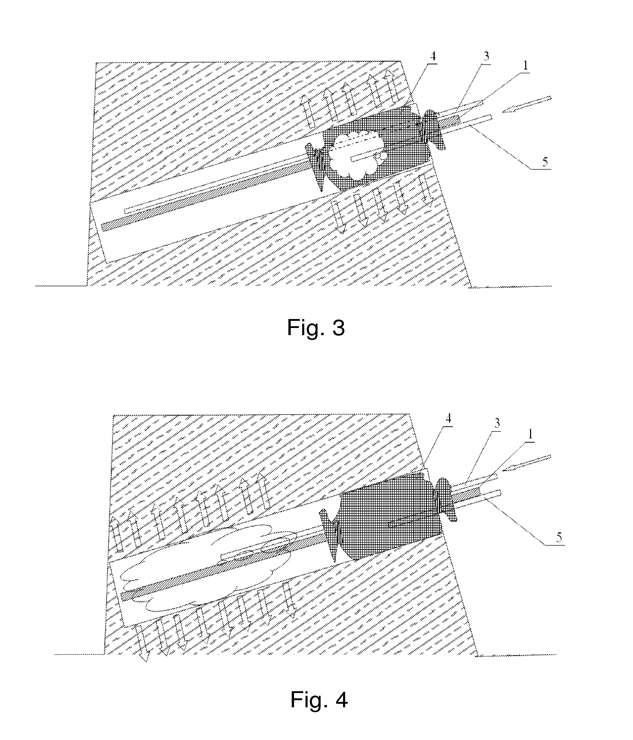
[0012]b) tying up a geotextile bag and grouting tubes on the anchoring rod body, wherein the geotextile bag and the grouting tubes are tied up on an end of the rod body, a bottom of the geotextile bag is provided on a border of an anchorage section and a free section when the geotextile bag is tied; a detachable grout inputting valve is mounted on an entrance of the grouting tube, wherein a connector between the grouting tube and a grout injector is fastened and sealed by a tube hoop; the grouting tubes comprises a first grouting tube which is a hole sealing grouting tube, and has an exit thereof provided in the geotextile bag, and a second grouting tube which is an anchoring grouting tube, and has an exit thereof provided at a bottom of a hole;
[0013]c) drilling holes, wherein the holes are drilled on positions needing supporting according to a design; and

Problems solved by technology

Although the conventional cement anchoring material in the world is widely utilized in engineering practices, there are still some problems therein such as complex processing of water-contained cement volume, high costs, inconvenient transportation and storage, and installation needing mechanical agitation.
A quality of the supporting with an immersed cement volume is lowered and wastes arises because most of additives added in the cement are deliquescent materials, the additives accelerates moisture and metamorphism of the cement, and thus shortens storage periods, lowers performance and even loses efficacy.
Additionally, the conventional cement anchoring material in the world utilizes a fixed composition and mixture ratio, and adjustments of a gelation time and strength at scene freely is difficult, therefore, the material can not adapt to changeable characteristics of the geotechnical engineering.
While application of a resin bonded anchor is limited because the resin material is poisonous, flammable, easy to aging, and high in price.
In fact, mixing ordinary cement mortar grout with the modified materials can not change the essence of water reactions, if water is involved, shrinkage after drying happens, anti-seismic and anti-crack capabilities are not sufficient and an improvement of the anchoring force is limited.
The conventional anchoring materials like cement mortar are difficult to adapt to requirements of the development of the anchorage technology because of the limited anchoring force, mediocre mechanical performance and insufficient deformation ability.

Method used


Image

  • Grouting method for anchoring with polymer
  • Grouting method for anchoring with polymer
  • Grouting method for anchoring with polymer

Examples


Embodiment Construction

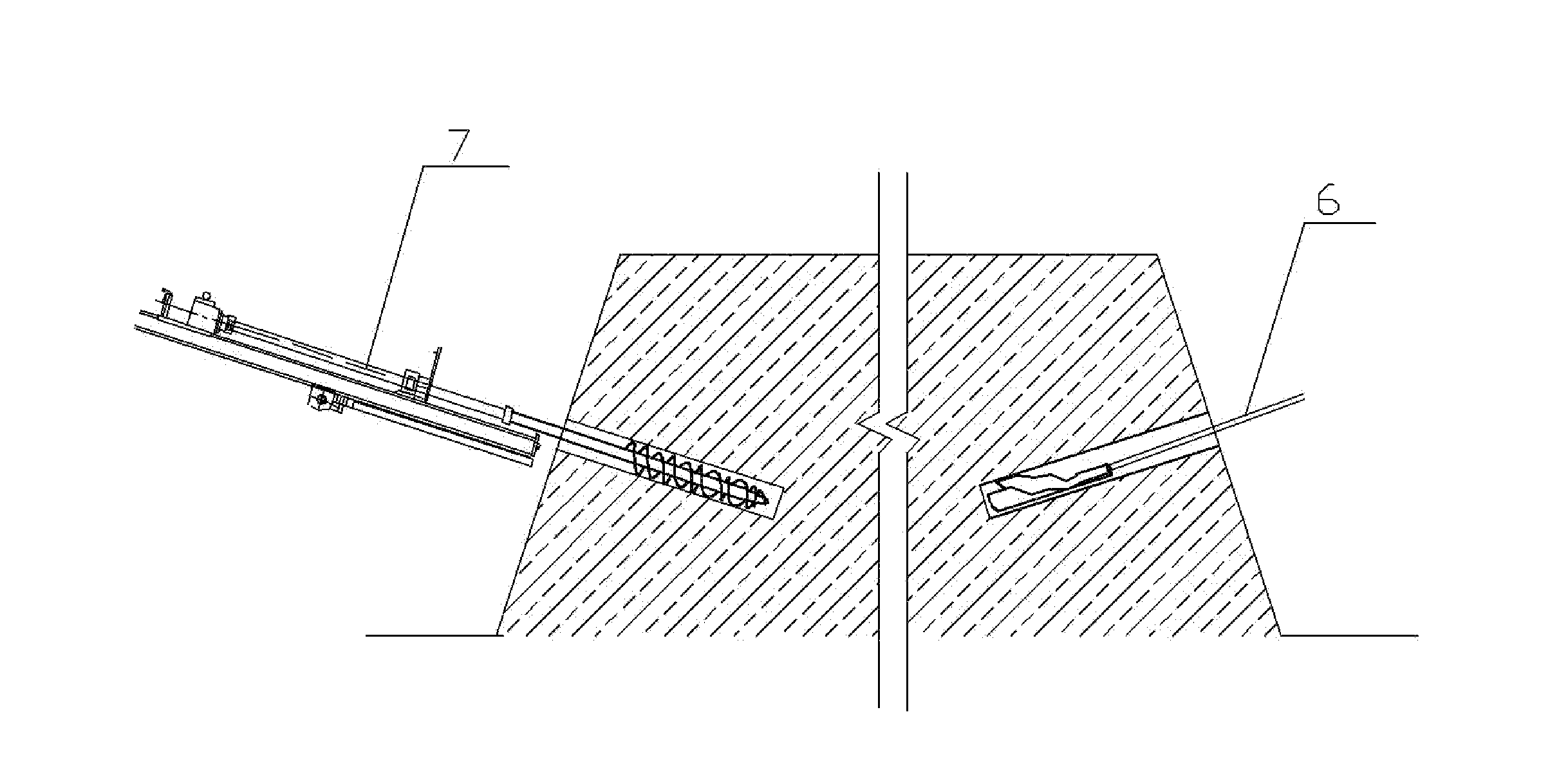
[0042]Referring to the drawings, the present invention is further illustrated:

[0043]a grouting method for anchoring with polymer comprises steps of:

[0044]a) processing a rod body, wherein a material of a rod body 1 is a rebar, a steel cable or other anchoring materials; wherein the rod body 1 is straightened, derusted and preserved at first, dirt such as oil and soils should be kept away from the rod body 1; raw materials are cut by an abrasive saw or a cutting machine and holders are welded according to design requirements, and centring holders 2 are provided every 0.5 m˜2 m on the rod body 1, the centring holders 2 may be provided every 0.5 m, 1 m, 1.5 m, 2 m or any length between 0.5 m˜2 m;

[0045]b) tying up a geotextile bag and grouting tubes on the anchoring rod body 1, wherein the geotextile bag 4 and the grouting tubes are tied up on an end of the rod body 1, a bottom of the geotextile bag4 is provided on a border of an anchorage section and a free section when the geotextile ...


PUM

PropertyMeasurementUnit
lengthaaaaaaaaaa
lengthaaaaaaaaaa
lengthaaaaaaaaaa

Abstract

A grouting method for anchoring with polymer is provided, wherein the method includes steps of: a) rod body processing; b) tying up a geotextile bag and grouting tubes on the anchoring rod body; c) hole drilling; d) polymer grouting: I. hole sealing grouting; II. anchoring grouting. The present invention has advantages of a sufficient adaptability, non-water reaction, convenient and fast construction, being economic, a high strength and a high durability. An expansive polymer material has an obvious compacting effect on soil, and is capable of increasing a friction force between a grout and a base; the water-proofing polymer material is an impermeable material for a steel rod body, and is of benefit to anti-corrosion and durability of the rod body; a solidifying time of the polymer material is short and no maintenance is needed in such a manner that construction periods are shortened.

Description

BACKGROUND OF THE PRESENT INVENTION[0001]1. Field of Invention[0002]The present invention relates to a technology field of reinforcing base facilities such as tunnels, foundations and side slopes, and more particularly to a method for grouting a polymer supporting anchor rod utilized in foundation pits, tunnels, side slopes, etc.[0003]2. Description of Related Arts[0004]In China, the development of the geotechnical anchorage technology began in late 50's of the 20th century, and at that time, the technology was mainly utilized in mine tunnel supporting engineering. In 60's, an anchor rod supporting technology was widely used in railway tunnel, water conservancy, side slope and underground engineering. Since 1970's, the earth anchor rods were widely used in deep foundation pit retaining engineering. Applications of anchorage technologies effectively guarantees the stability of an internal stress field of a rock and soil mass, improves an internal mechanical state of the rock and soil...

Claims


Application Information

Patent Timeline
Patent Type & Authority Patents(United States)
IPC IPC(8): E21D20/02E21D20/00E21D21/00
CPCE21D21/00E21D20/003E21D20/025E21D20/028
Inventor WANG, FUMINGSHI, MINGSHENGGUO, CHENGCHAOCHEN, HONGLIANGZHAO, DONGKAIHE, LEIYING
Owner WANG FUMING
Learn More