Sheet-metal composite, method for joining sheets and joining device

a technology of sheet metal and composite, which is applied in the direction of sheet joining, soldering auxillary devices, furniture joining, etc., can solve the problems of voluminous and inflexible edging devices for subsequently shaping the flange, limited flange geometries, and high cost of complex edging sequences

Active Publication Date: 2015-04-14
KOPIN CORPORATION
View PDF23 Cites 70 Cited by
  • Summary
  • Abstract
  • Description
  • Claims
  • Application Information

AI Technical Summary

Benefits of technology

[0005]It is an object of certain aspects of the invention to improve the joining of component parts, at least one of which is a metal sheet, with regard to its flexibility with respect to the progression of a flanging edge and the strength of the composite.

Problems solved by technology

If the flanges are shaped while still in the press, then limits are placed on the flange geometries which can be produced, due to the need to remove the part from the mold.
Edging devices for subsequently shaping the flanges are voluminous and inflexible.
Furthermore, complex edging sequences can only be achieved at great cost.

Method used


Image

  • Sheet-metal composite, method for joining sheets and joining device
  • Sheet-metal composite, method for joining sheets and joining device
  • Sheet-metal composite, method for joining sheets and joining device

Examples


Embodiment Construction

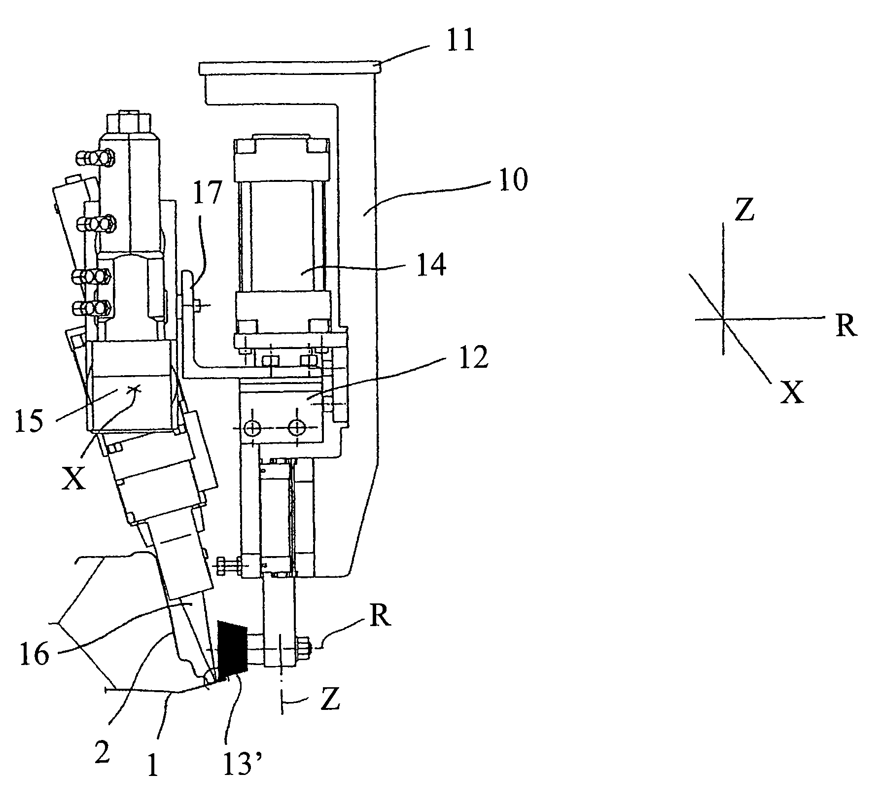
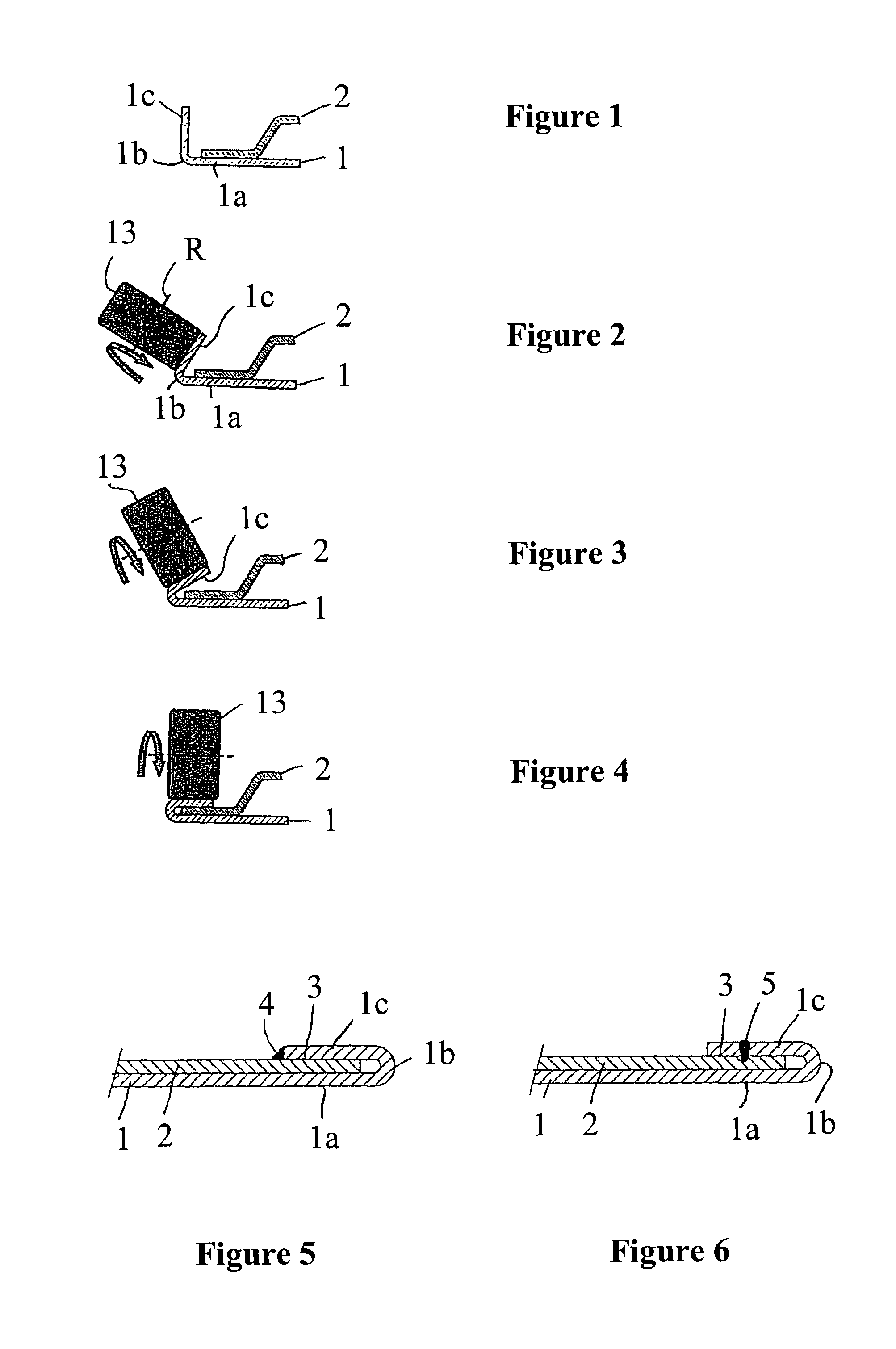
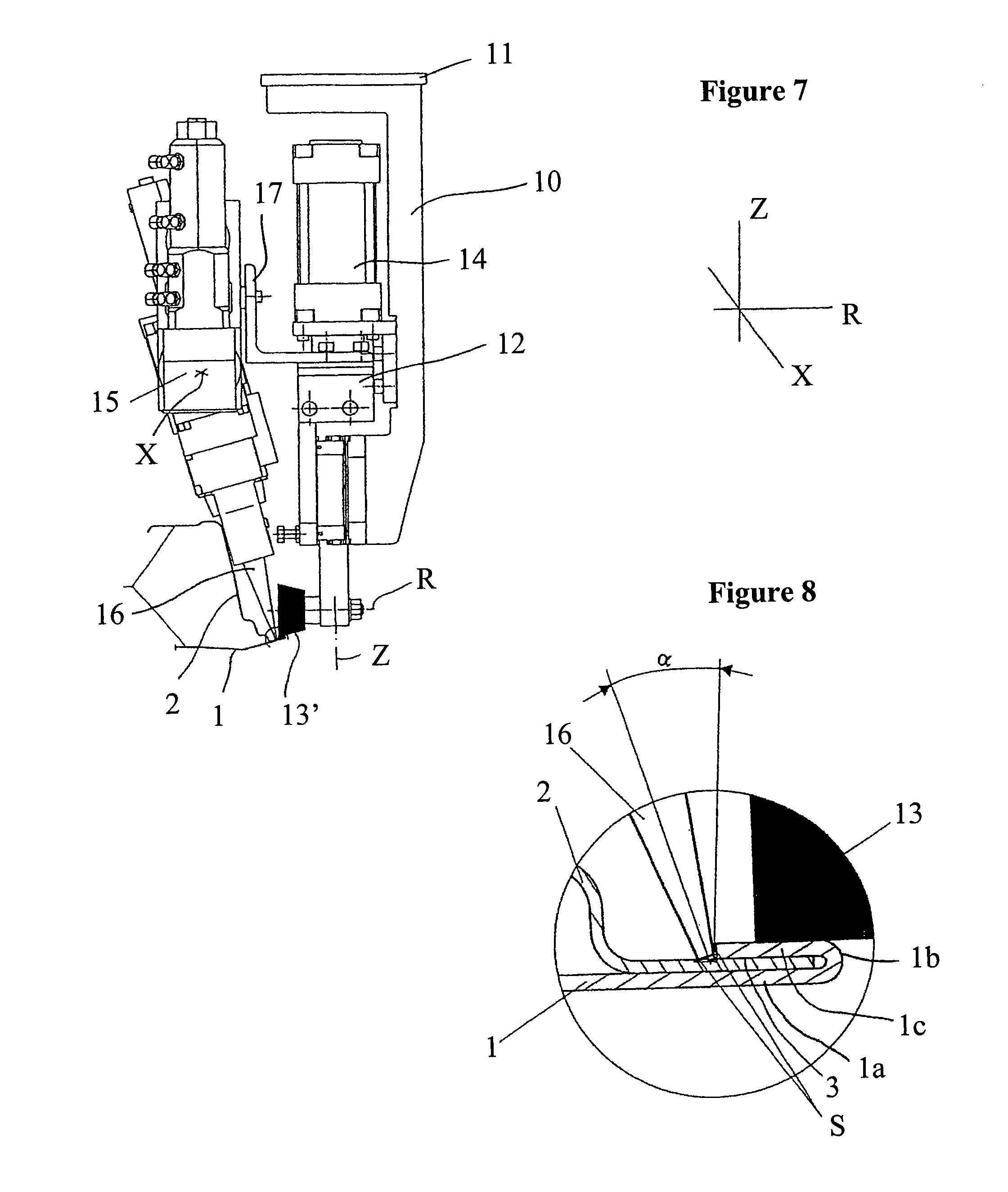
[0042]FIGS. 1 to 4 show a method sequence in which a metal sheet composite is manufactured by roll-flanging. Each figure shows a cross-section of a peripheral region of an inner metal sheet 2 and an outer metal sheet 1 which are fixed relative to each other in a joining position by means of a chucking device. In a preceding process of plastic reshaping, for example deep-drawing, the metal sheets 1 and 2 have acquired their final shape as desired for the respective connection, except for the subsequent reshaping which is still required for connecting. Both metal sheets 1 and 2 are three-dimensionally warped structures which each comprise a flange suited to the hemming connection in the joining region shown, wherein the flange of the inner metal sheet 2 is pressed against the outer metal sheet 1 over an area by the chucking device. In an outer metal sheet region 1a, the outer metal sheet 1 transitions into a flange 1c via a sharp bend 1b. The flange 1c is successively folded over comp...


PUM

PropertyMeasurementUnit
distanceaaaaaaaaaa
distanceaaaaaaaaaa
distancesaaaaaaaaaa

Abstract

A metal sheet composite comprising an outer metal sheet having a flange which is folded over around a flanging edge; an inner metal sheet which forms a joint with the flange; and a welding or soldering seam which is produced on or in the joint and fixedly connects the metal sheets to each other. A method for joining metal sheets and a device for flanging and welding or soldering are also disclosed. The device includes: a tool head; a flanging member, arranged on the tool head, for roll-flanging or slide-flanging; and a welding or soldering tool arranged on the tool head, wherein the flanging member and the welding or soldering tool are arranged such that the flanging member forms a pressing means for a welding or soldering process which can be performed using the welding or soldering tool.

Description

[0001]This application is the U.S. national phase application of PCT International Application No. PCT / EP2008 / 000227, filed Jan. 14, 2008, which claims priority to German Patent Application No. DE102007002856.5, filed Jan. 15, 2007, the contents of such applications being incorporated by reference herein in their entirety.FIELD OF THE INVENTION[0002]The invention relates to joining component parts, in particular metal sheets, including a welding or soldering process.BACKGROUND OF THE INVENTION[0003]Welding and soldering are proven joining methods for metallic component parts. In an automated welding or soldering process, the component parts to be joined are fixed in a joining position and pressed against each other near the current welding or soldering point using a pressing means—for example, a pressing finger or pressing roller—during the welding or soldering, wherein the pressing means together with the welding or soldering tool travels a joining region of the component parts in ...

Claims


Application Information

Patent Timeline
Patent Type & Authority Patents(United States)
IPC IPC(8): B23K26/00B21D39/02B23K1/00B23K1/005B23K26/02B23K33/00F16B5/08
CPCB23K33/008B21D39/021B21D39/023B23K1/0008B23K1/0056B23K26/023F16B5/08B23K2201/006B23K2201/18B23K26/037Y10T29/53791B23K2101/006B23K2101/18
Inventor SCHNEEGANS, JOCHENKRAFT, MARTIN
Owner KOPIN CORPORATION
Why Eureka
Try Eureka