Metal joint body and apparatus for manufacturing the metal joint body

a technology of metal joints and metal joints, which is applied in the direction of fastening means, thin material handling, securing devices, etc., can solve the problems of easy breakage of press joints and inability to form press joints, and achieve the effect of improving electrical characteristics and reliability

Active Publication Date: 2017-09-14
YAZAKI CORP
View PDF2 Cites 0 Cited by
  • Summary
  • Abstract
  • Description
  • Claims
  • Application Information

AI Technical Summary

Benefits of technology

[0011]According to the present invention, by cutting two or more overlapped metal sheets along the first cutting line and the pair of second cutting lines extending so as to intersect the first cutting line at each end of the first cutting line and pressing the areas surrounded. with the first cutting line and the pair of second cutting lines and each of the pair of bending lines connecting both ends of the pair of second cutting lines so as to bend the each area about the bending line, the first cutting line is arranged between the pair of bending lines, so that the miniaturized metal joint body is manufactured along the direction of the row of the pair of bending lines.
[0012]According to the present invention, because each width of the projecting member and the hole along the direction parallel to the first cutting line is increasing toward the first cutting line, the projecting member is pushed into the hole. Thereby, in the outer surrounding cutting surface of the projecting member and the inner surrounding cutting surface of the hole, normal load is generated. Therefore, joining of the metal contact area is advanced, so that the electric characteristics and reliability thereof are improved.
[0013]In the die by prior art, a pair of press jig is arranged with a space therebetween at positions corresponding to each one of the pair of projecting members. According to the present invention, in the apparatus, one press projection die for forming the pair of projecting members is provided. Therefore, the press projection die can be formed with an enough size, so that the apparatus for manufacturing the metal joint body can be provided with the press projection die having improved strength.

Problems solved by technology

The die is provided with the pair of press jigs arranged with a space therebetween, so that the press jigs cannot be formed to have enough strength, and the press jigs may be easily broken.

Method used


Image

  • Metal joint body and apparatus for manufacturing the metal joint body
  • Metal joint body and apparatus for manufacturing the metal joint body
  • Metal joint body and apparatus for manufacturing the metal joint body

Examples


first embodiment

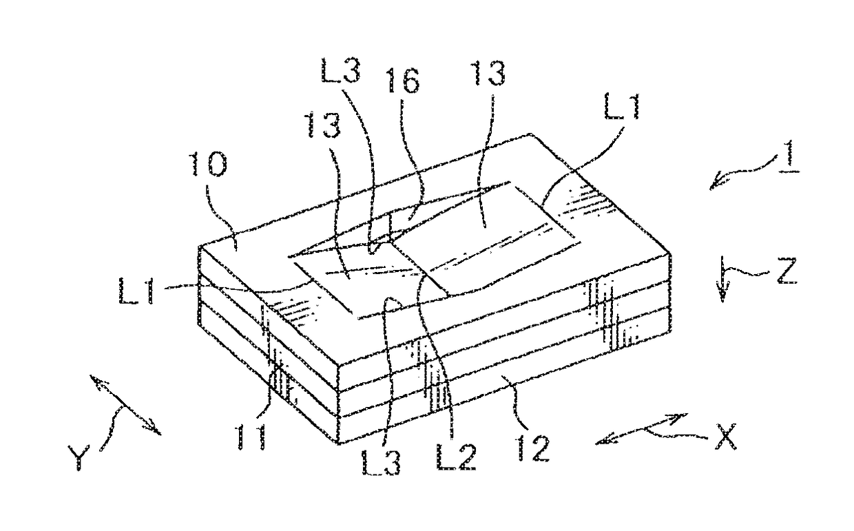
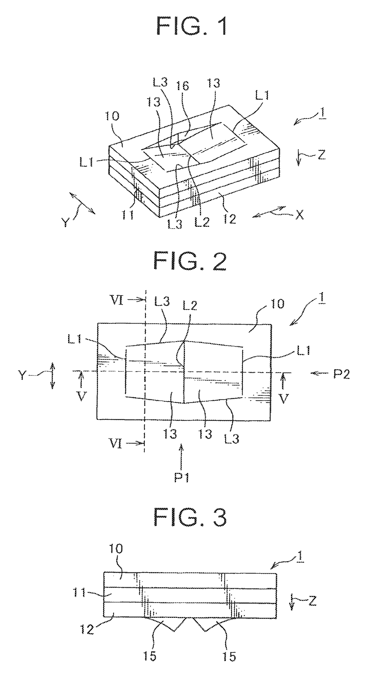
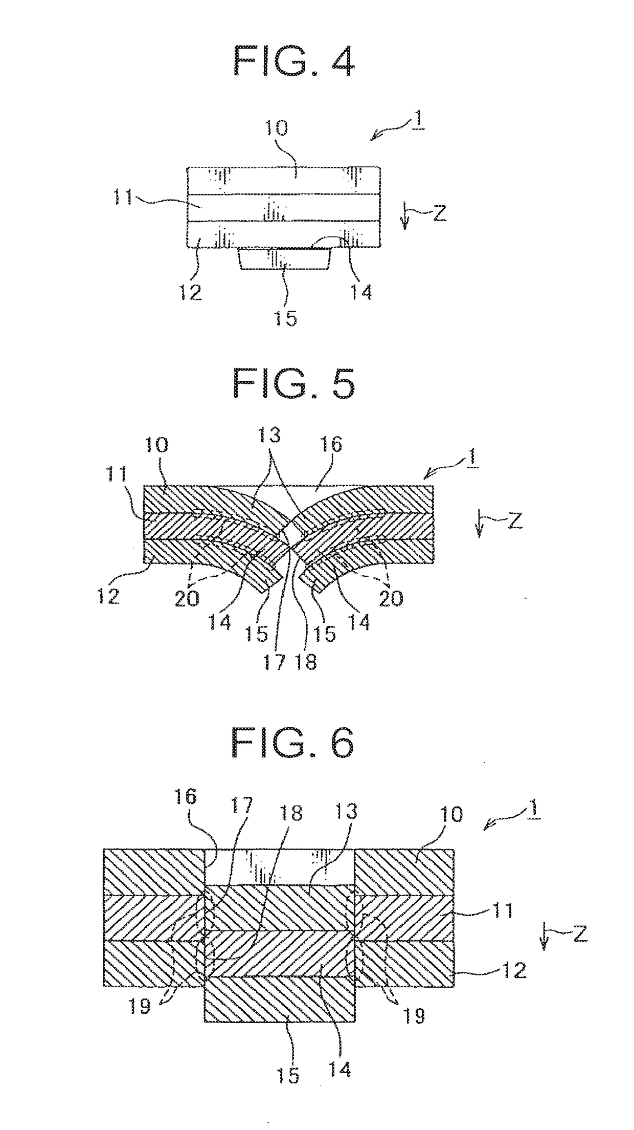
[0026]A metal joint body of a first embodiment according to the present invention is described with reference to FIGS. 1-6.

[0027]As shown in FIGS. 1-6, the metal joint body 1 includes three metal sheets 10, 11, 12 structured with, for example, the same material and the same thickness. As shown in FIGS. 5, 6, the metal joint boy 1 includes projecting members 13, 14, 15 and holes 16, 17, 18 and metal contact areas 19, 20.

[0028]Pairs of projecting members 13, 14, 15 are provided at each of metal sheets 10, 11, 12. Each of the pairs of projecting members 13, 14, 15 is formed by cutting three overlapped metal sheets 10, 11, 12 along a first cutting line L2 and a pair of second cutting lines L3 extending so as to intersect the first cutting line L2 at each end of the first cutting line L2 and pressing areas surrounded with the first cutting line L2 and the pair of second cutting lines L3 and each of a pair of bending lines L1 connecting both ends of the pair of second cutting lines L3 so ...


PUM

PropertyMeasurementUnit
areasaaaaaaaaaa
pressureaaaaaaaaaa
residual stressaaaaaaaaaa

Abstract

A miniaturized metal joint body and an apparatus for manufacturing the metal joint body to be improved about strength are provided. By cutting three overlapped metal sheets along a first cutting line and a pair of second cutting lines extending so as to intersect the first cutting line at each end of the first cutting line and pressing areas surrounded with the first cutting line and the pair of second cutting lines and each of a pair of bending lines connecting both ends of the pair of second cutting lines, each of the pairs of projecting members is formed so as to project in a pressing direction of arrow z.

Description

TECHNICAL FIELD[0001]This invention relates to a metal joint body and an apparatus for manufacturing the metal joint body, especially a metal joint body which is formed by joining two or more metal sheets to each other, and an apparatus for manufacturing the metal joint body by joining two or more metal sheets to each other.BACKGROUND ART[0002]In general, a method of clamping and adhering metal sheets to each other by pressure is known as a method for joining metal sheets to each other. The joining by adhering by pressure depends on residual stress by clamping and contact, so that electric characteristics thereof are not satisfied. At a contact area of the metal sheets, there are many gaps so that it is has a problem that the electric characteristics cannot be easily maintained in a long period because of corrosion. For maintaining the electric characteristics, it is considerable to welding the metal sheets to each other by melting the metal sheets with gas or plasma. It is not easi...

Claims


Application Information

Patent Timeline
Patent Type & Authority Applications(United States)
IPC IPC(8): B21D39/03
CPCB21D39/03F16B5/045F16B2001/0064Y10T428/12368F16B2200/93
Inventor MURAKAMI, KAZUHIROWATANABE, YOSHIHIKO
Owner YAZAKI CORP
Why Eureka
Try Eureka