Pressing system, laser-joining system, and method

a laser-joining system and pressing system technology, applied in the direction of soldering apparatus, manufacturing tools,auxillary welding devices, etc., can solve the problem that the contact pressure with which the mask is pressed against the parts to be joined increases linearly with the number

Active Publication Date: 2018-05-31
MANZ
View PDF0 Cites 0 Cited by
  • Summary
  • Abstract
  • Description
  • Claims
  • Application Information

AI Technical Summary

Benefits of technology

[0010]The problem addressed by the present invention is therefore that of providing a pressing system for a laser-joining system as well as a laser-joining system and a method, with the aid of which the joining of parts to be joined by means of a laser-joining system is improved.

Problems solved by technology

The disadvantage thereof, on the one hand, is that such a pressing system requires a mask which is individually matched to the particular joining task.
Moreover, it is problematic that, in the case of a large number of joining points, for example several hundred or thousand joining points, as is the case, for example, with high-performance current accumulators, the necessary contact pressure with which the mask must be pressed against the parts to be joined increases linearly with the number of joining points.

Method used


Image

  • Pressing system, laser-joining system, and method
  • Pressing system, laser-joining system, and method
  • Pressing system, laser-joining system, and method

Examples


Embodiment Construction

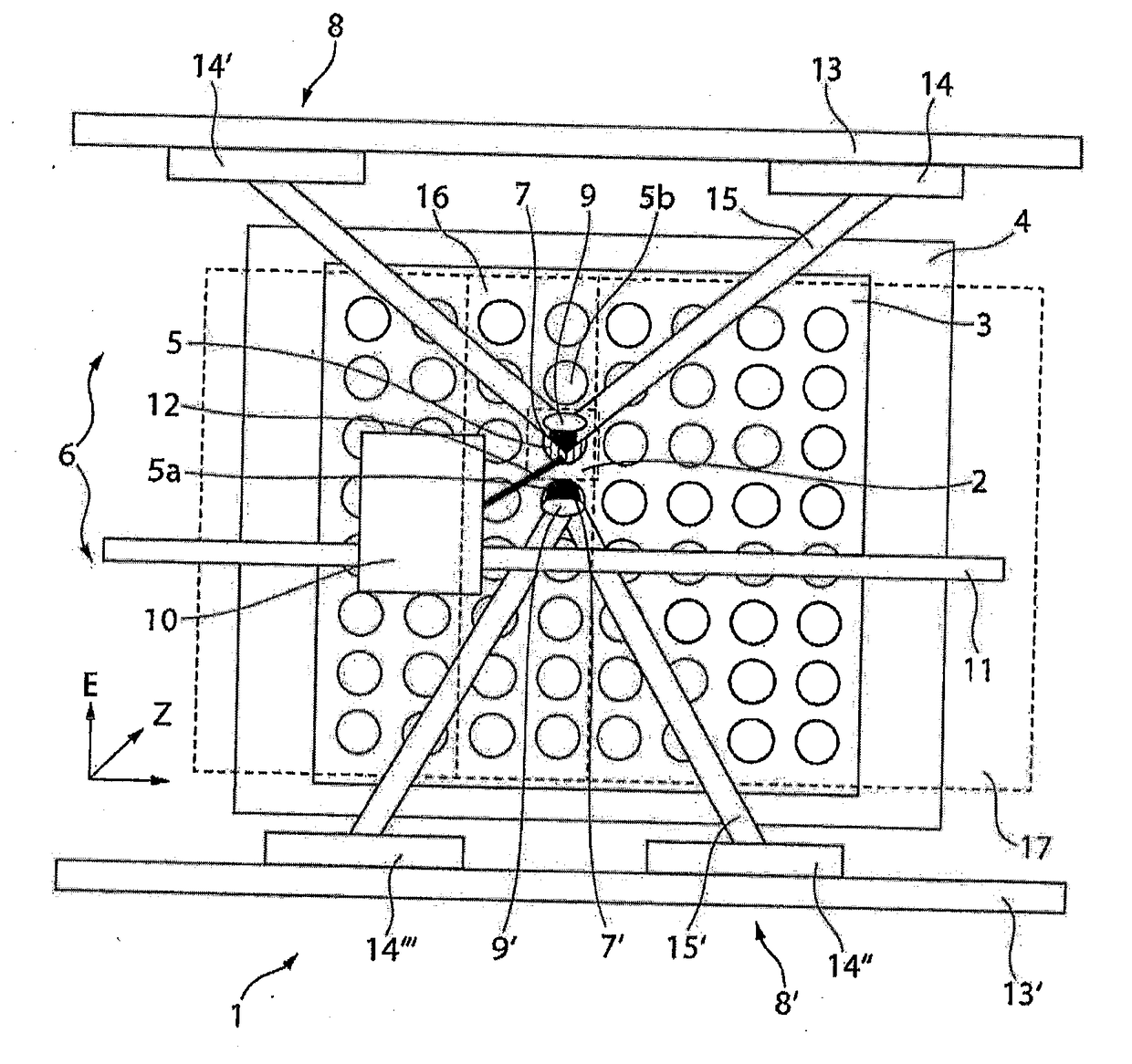
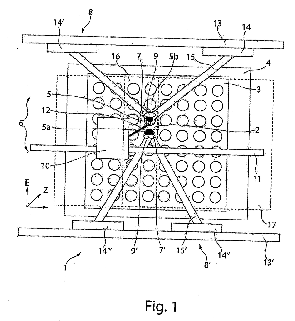
[0069]The design and the mode of operation of a laser joining system and of the method according to the invention are to be described in greater detail, by way of example, on the basis of the production of a current accumulator.

[0070]For this purpose, FIG. 1 shows a laser joining system 1 comprising a storage cell 2 which is to be laser-joined, in particular laser-welded, onto a base plate 3.

[0071]The laser joining system 1 comprises a receptacle 4. In the receptacle 4, the base plate 3 and, therebelow, (not visible in the top view from FIG. 1 and therefore represented merely using dashed lines), the storage cell 2 are disposed at a first joining point 5. It is understood that a plurality of storage cells are disposed under the base plate 3 at a plurality of joining points, in order to attain a high storage capacity of the current accumulator, and the storage cells are to be joined with the base plate 3. In particular, a second joining point 5a and a third joining point 5b are repre...


PUM

PropertyMeasurementUnit
areaaaaaaaaaaa
contact pressureaaaaaaaaaa
temperatureaaaaaaaaaa

Abstract

A pressing system for a laser joining system for pressing together parts to be joined (storage cell, base plate) in the area of a joining point, includes a receptacle for accommodating the parts to be joined, a pressing element for locally pressing together the parts to be joined, in the area of the joining point, and a positioning system for the relative positioning of the pressing element and the receptacle and for pressing together the parts to be joined, during the joining process. The positioning system includes a parallel positioning device for the relative positioning of the receptacle and the pressing element in parallel to a plane (E), and an oblique positioning device for the relative positioning of the pressing element and the receptacle obliquely, in particular transversely, with respect to the plane (E) and for pressing together the parts to be joined, during the joining process.

Description

CROSS REFERENCE TO RELATED APPLICATIONS[0001]Applicant claims priority under 35 U.S.C. § 119 of European Application No. 16200637.3 filed on Nov. 25, 2016, the disclosure of which is incorporated by reference.BACKGROUND OF THE INVENTION[0002]The invention relates to a pressing system for a laser-joining system for pressing together parts to be joined, in the area of a joining point.[0003]Devices for pressing on the parts to be joined are usually utilized for connecting parts to be joined by means of laser joining.[0004]This also relates, in particular, to the production of current accumulators.[0005]Modern current accumulators consist of a plurality of storage cells which are disposed on a shared base plate and are joined together therewith at joining points, in particular by means of laser joining. A base plate in this sense can be, for example, circuit boards or connection plates for forming one of the poles (positive or negative poles) or a measuring point of the current accumula...

Claims


Application Information

Patent Timeline
Patent Type & Authority Applications(United States)
IPC IPC(8): B23K26/08B23K26/02B23K26/20B23K26/22
CPCB23K26/0861B23K26/02B23K26/206B23K26/22B23K26/70B23K26/20B23K2101/36B23K37/0229B23K37/0408B23K26/037
Inventor FREUNDT, MARTINNEHER, RALFSCHMIEDER, BENJAMIN
Owner MANZ
Why Eureka
Try Eureka