Solid electrolytic capacitor
a technology of electrolytic capacitors and solids, which is applied in the direction of fixed capacitor details, casings/cabinets/drawers, electrical apparatus casings/cabinets/drawers, etc., can solve the problems of failure, coating resin leakage, and difficulty in providing stable fillet formation, so as to prevent delamination and stable fillet formation
- Summary
- Abstract
- Description
- Claims
- Application Information
AI Technical Summary
Benefits of technology
Problems solved by technology
Method used
Image
Examples
first exemplary embodiment
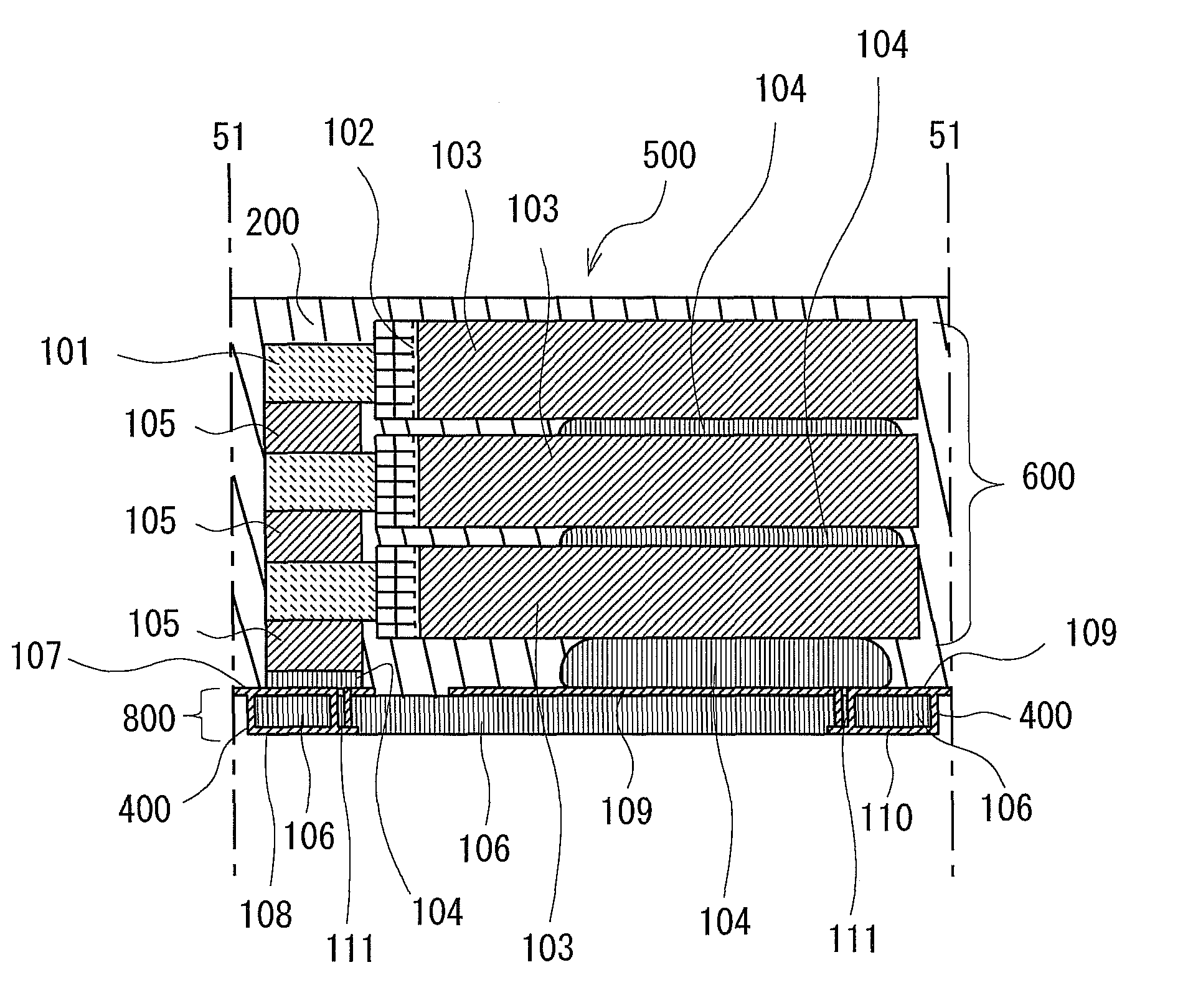
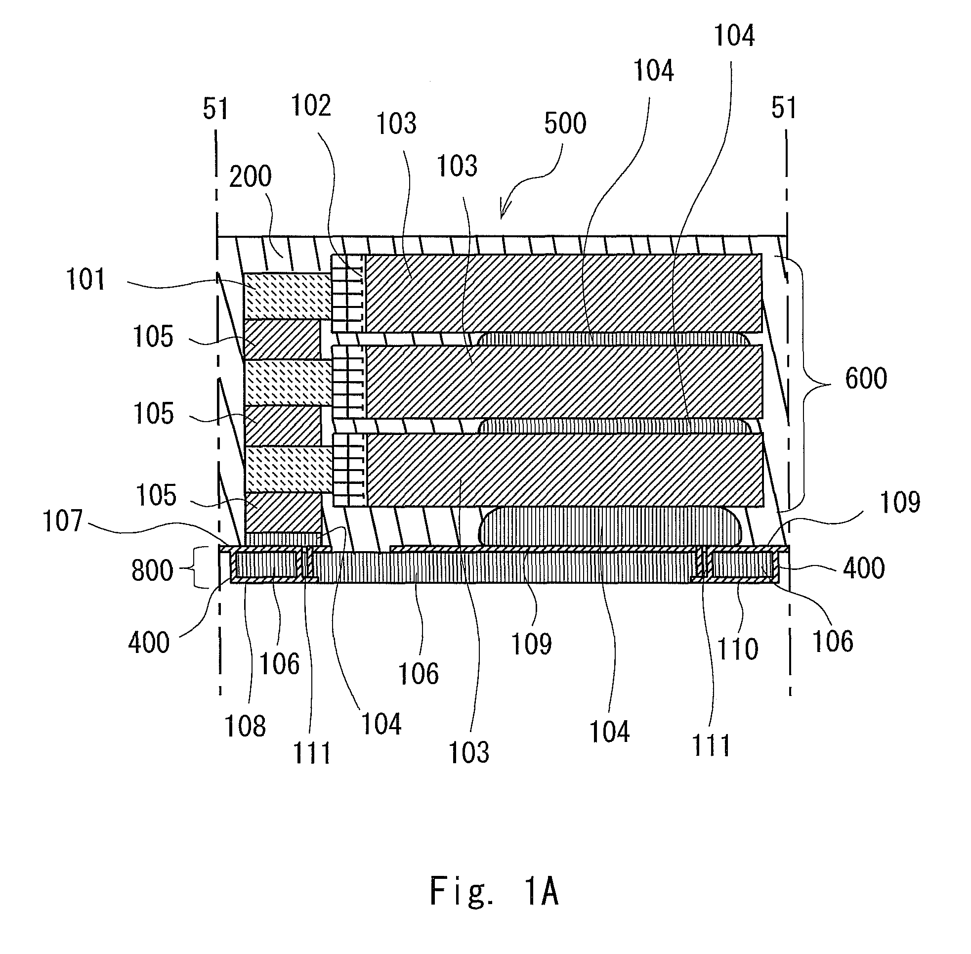
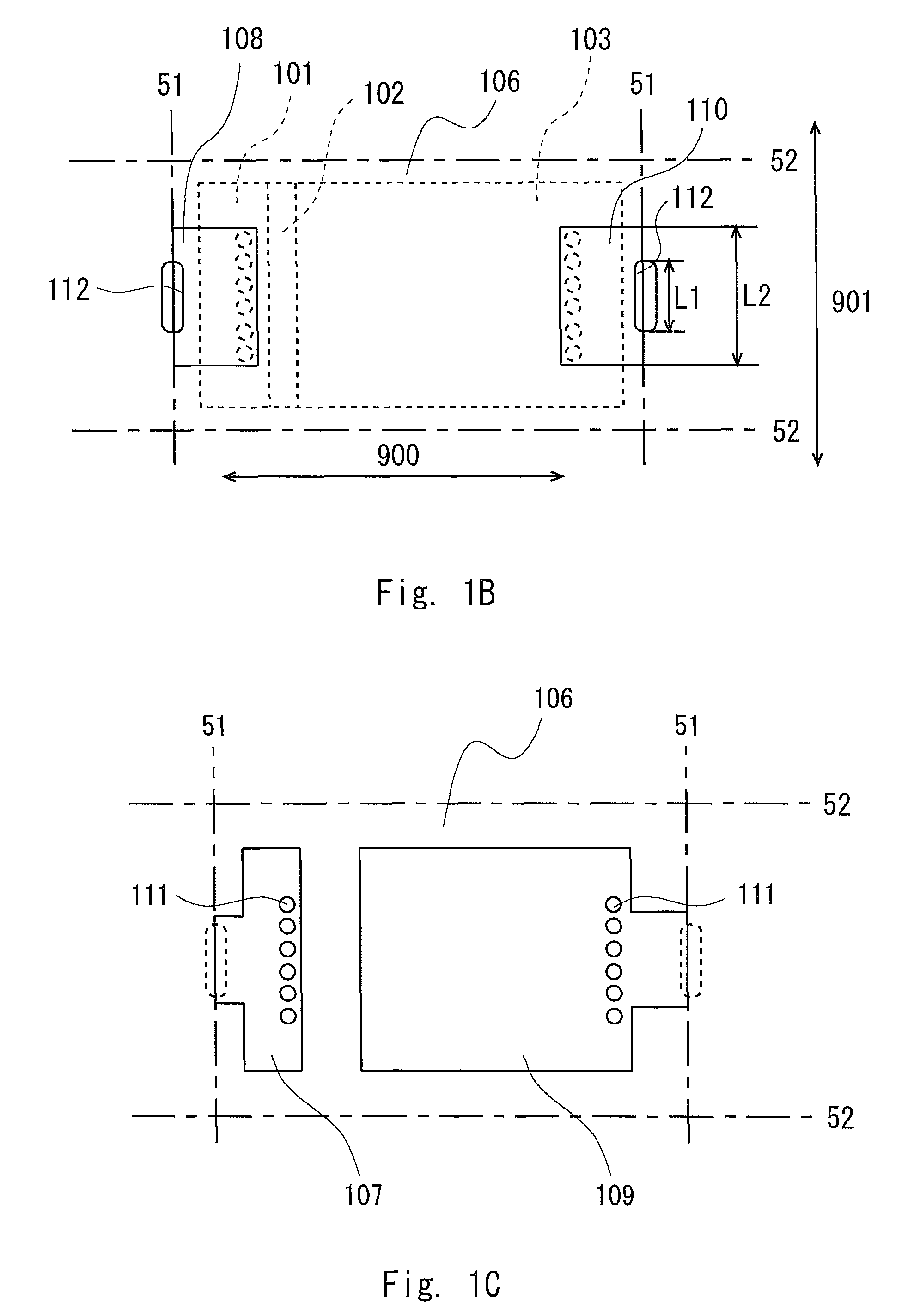
[0041]A first embodiment is explained using FIGS. 1A to 1D and FIGS. 5A and 5B.
[0042]FIGS. 1A to 1D are views showing a solid electrolytic capacitor according to the first embodiment of the present invention. FIG. 1A is a cross-sectional diagram of one solid electrolytic capacitor. FIG. 1B is a product bottom view viewed from a mounting electrode side. FIG. 1C is a top view viewed from an electrode terminal for element connection side. FIG. 1D is an enlarged diagram of a code 112 part of FIG. 1B.
[0043]A solid electrolytic capacitor 500 can be obtained by the manufacture as described below. First, a capacitor element is manufactured. The capacitor element includes one capacitor element anode part (anode part) 101 of an anode body including a linear, foil-like, or plate-like valve metal and a capacitor element cathode part (cathode part) 103 including a dielectric layer, a solid electrolyte layer, a graphite layer, and a silver paste layer, which are sequentially formed to the other s...
second exemplary embodiment
[0060]A second embodiment is explained using FIGS. 2A to 2C.
[0061]FIGS. 2A to 2C show the configuration of a solid electrolytic capacitor according to the second embodiment of the present invention. FIG. 2A is a cross-sectional diagram of one solid electrolytic capacitor. FIG. 2B is a product bottom view viewed from the mounting electrode side. FIG. 2C is a top view viewed from the electrode for element connection.
[0062]As the manufacture of the capacitor stack element 600 is same as the first embodiment, the explanation is omitted here. As shown in FIG. 2A, there are three terminals of the mounting electrode in the electrode substrate 800 of this embodiment.
[0063]That is, a second cathode terminal 110b of the mounting electrode side is placed at a position spaced with an interval R in the first direction 900 from a first cathode terminal 110a of the mounting electrode side (which is mounting electrode side cathode terminal 110 of the first embodiment). This second cathode terminal ...
third embodiment
[0070]A third embodiment is explained using FIGS. 3A and 3B.
[0071]FIG. 3A is a product bottom view viewed from the mounting electrode side. FIG. 3B is a top view viewed from the electrode for element connection.
[0072]As compared with the second embodiment, in the third embodiment, there is no recessed parts 112c and 112d, and although the second cathode terminal 110b and the cathode terminal for element connection 109 extend in the second direction 901 but not up to the cutout line 52 and stops before the cutout line 52.
[0073]Other configuration is the same as the second embodiment. Note that there is no difference observed in the ESL value between the second and the third embodiments.
PUM
| Property | Measurement | Unit |
|---|---|---|
| thickness | aaaaa | aaaaa |
| length | aaaaa | aaaaa |
| length | aaaaa | aaaaa |
Abstract
Description
Claims
Application Information
 - R&D
- Intellectual Property
- Life Sciences
- Materials
- Tech Scout
- Unparalleled Data Quality
- Higher Quality Content
- 60% Fewer Hallucinations
Browse by: Latest US Patents, China's latest patents, Technical Efficacy Thesaurus, Application Domain, Technology Topic, Popular Technical Reports.
© 2025 PatSnap. All rights reserved.Legal|Privacy policy|Modern Slavery Act Transparency Statement|Sitemap|About US| Contact US: help@patsnap.com


