Communicating with MIPI-compliant devices using non-MIPI interfaces

a technology of communication interface and mipi, applied in the field of electronic devices, can solve the problems of prohibitively expensive provisioning of converter chips, insufficient support of all the desired different communications,

Active Publication Date: 2015-04-14
LATTICE SEMICON CORP
View PDF6 Cites 25 Cited by
  • Summary
  • Abstract
  • Description
  • Claims
  • Application Information

AI Technical Summary

Problems solved by technology

Other devices, include FPGAs, may have some MIPI D-PHY interfaces, but not enough to support all of the desired different communications.
For some applications, the provisioning of such converter chips is prohibitively expensive.

Method used


Image

  • Communicating with MIPI-compliant devices using non-MIPI interfaces
  • Communicating with MIPI-compliant devices using non-MIPI interfaces
  • Communicating with MIPI-compliant devices using non-MIPI interfaces

Examples


Embodiment Construction

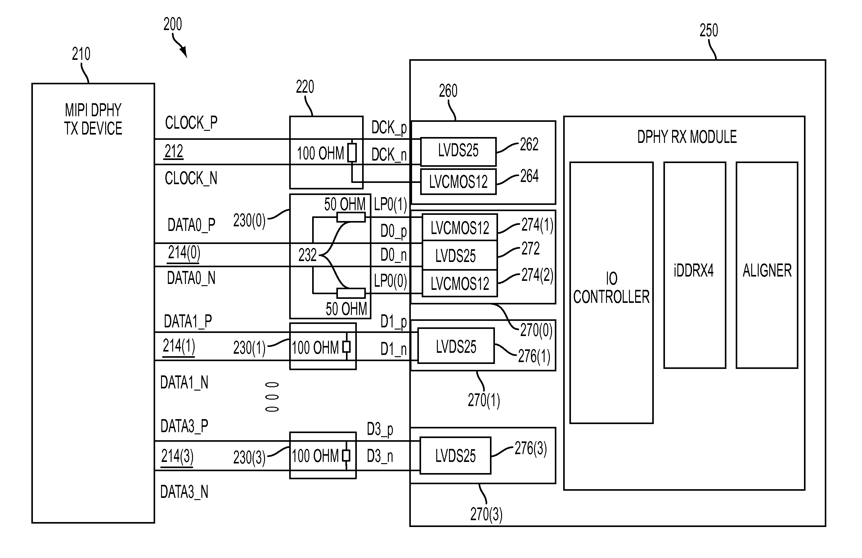
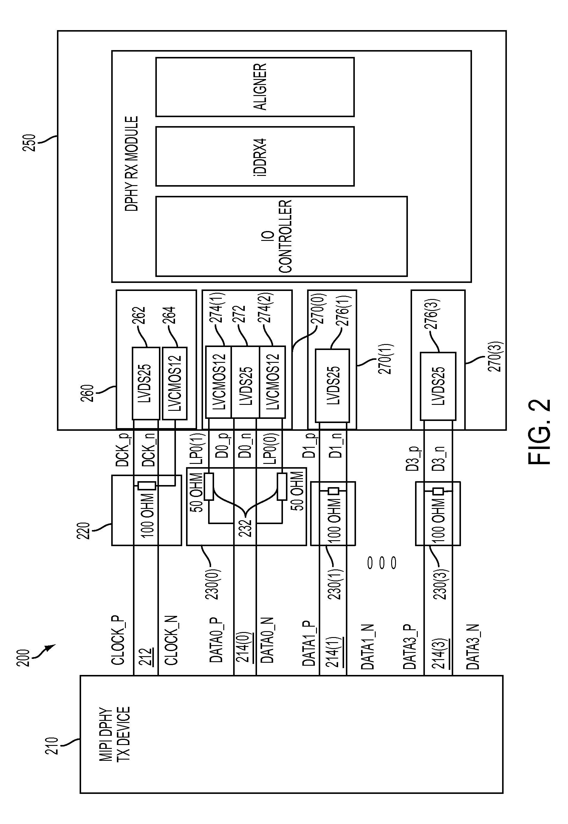
[0023]FIG. 2 shows a high-level block diagram of an electronic system 200 that enables a MIPI-compliant transmit (TX) device 210, such as a MIPI camera or other MIPI-compliant video source, to communicate with a field-programmable gate array (FPGA) 250 without using any MIPI-compliant I / O (input / output) interfaces on the FPGA. Depending on the particular situation, the FPGA 250 might not have any MIPI-compliant I / O interfaces or it might have some, but not have enough MIPI-compliant I / O interfaces to support communications with MIPI TX device 210, perhaps because it is also connected to other MIPI-compliant devices (not shown in FIG. 2) using its MIPI-compliant I / O interfaces. The configuration of FIG. 2 conforms to the Camera Serial Interface 2 (CSI-2) and Display Serial Interface (DSI) MIPI protocols.

[0024]As shown in FIG. 2, FPGA 250 does have various other, non-MIPI-compliant I / O interfaces, i.e., low-voltage differential signaling (LVDS) and low-voltage complementary metal oxid...


PUM


Abstract

Using relatively inexpensive, external resistor networks, an electronic device, such as an FPGA, can be configured to use non-MIPI interfaces to communicate with one or more MIPI-compliant devices, such as video sources (e.g., cameras) and sinks (e.g., displays). High-speed (HS) and low-power (LP) MIPI signaling for each MIPI clock/data lane is supported by a set of one or more non-MIPI interfaces, such as LVDS and/or LVCMOS receivers, transmitters, and/or transceivers, and an appropriate, corresponding, external resistor network. For configurations in which the resistor-configured electronic device can handle high-speed MIPI data from a MIPI-compliant device, the electronic device can detect transitions in the MIPI mode of the MIPI-compliant device. In some configurations, the resistor-configured electronic device can provide high-speed MIPI data to a MIPI-compliant device. In either case, the electronic device configures the non-MIPI interfaces to support the current MIPI HS/LP mode.

Description

CROSS-REFERENCE TO RELATED APPLICATIONS[0001]This application is a continuation of U.S. application Ser. No. 14 / 220,377, filed Mar. 20, 2014, which claims the benefit of the filing date of U.S. Provisional Application No. 61 / 925,792, filed Jan. 10, 2014, both of which are incorporated herein by reference in their entirety.BACKGROUND[0002]1. Field of the Invention[0003]The present invention relates to electronics and, more specifically but not exclusively, to electronic devices communicating using signals conforming to the Mobile Industry Processor Interface (MIPI) specification.[0004]2. Description of the Related Art[0005]This section introduces aspects that may help facilitate a better understanding of the invention. Accordingly, the statements of this section are to be read in this light and are not to be understood as admissions about what is prior art or what is not prior art.[0006]The Mobile Industry Processor Interface (MIPI) differential physical (D-PHY) specification dictate...

Claims


Application Information

Patent Timeline
Patent Type & Authority Patents(United States)
IPC IPC(8): G06F13/42
CPCG06F13/4286Y02D10/00G06F13/4221
Inventor MARENA, TEODOROJENNINGS, GRANT
Owner LATTICE SEMICON CORP
Why Eureka
Try Eureka