Flow-rate measurement system

a flow rate and measurement system technology, applied in the direction of volume flow measurement devices, liquid/fluent solid measurement, volume/mass flow by differential pressure, etc., can solve the problems of diversity, measurement uncertainties or even measurement errors, and always burdening one of the parties involved in measuring tolerance, etc., to achieve the effect of convenient self-monitoring

Active Publication Date: 2015-04-21
KRONE GMBH
View PDF16 Cites 5 Cited by
  • Summary
  • Abstract
  • Description
  • Claims
  • Application Information

AI Technical Summary

Benefits of technology

[0009]Accordingly, a primary object of the invention is to provide a flow-rate measurement system which easily allows self-monitoring.
[0020]Furthermore, the type of flow rate measurement can also differ from one another in the specific implementation of the same measurement principle. Therefore, one configuration calls for the first flow meter and the second flow meter to each be an ultrasonic flow meter with one measurement tube, the first flow meter and the second flow meter differing from one another at least with respect to the path of the ultrasonic signals in the respective measurement tube. Thus, in one flow meter, the ultrasonic transducers are located opposite one another at different locations of the measurement tube so that they convert the ultrasonic signals directly from ultrasonic transducer to ultrasonic transducer. For the other flow meter, the ultrasonic transducers are on the same side of the measurement tube and the ultrasonic signals, after emission, undergo a reflection on the wall of the measurement tube and are then detected only by the other ultrasonic transducer. The path of the ultrasonic signals which differs in terms of length also yields a different evaluation or a different dependency on the measurement conditions. This in turn has the advantage that errors or perturbations do not act in the same way in the two flow meters, but remain detectable by their difference.
[0024]In one advantageous configuration, it is provided that one measurement tube of the first flow meter and one measurement tube of the second flow meter are located directly next to one another and are connected to one another. This yields a very short construction of the system. Conventionally, between different measurement devices, space is left in the form of a normal pipe section. In this configuration, however, the flow meters are located directly flange on flange and are connected to one another.

Problems solved by technology

Measurement tolerances are always a burden to one of the parties involved, usually to the burden of the supplier.
Based on the changing measurement conditions or ageing phenomena of the measurement devices, however, measurement uncertainties or even measurement errors can arise.
The disadvantage in these systems is that the diversity must be combined again; this can be associated with difficulties.
This process is very complex since these systems can be heavy and since provisions must be made for the required bypasses.

Method used


Image

  • Flow-rate measurement system
  • Flow-rate measurement system

Examples


Embodiment Construction

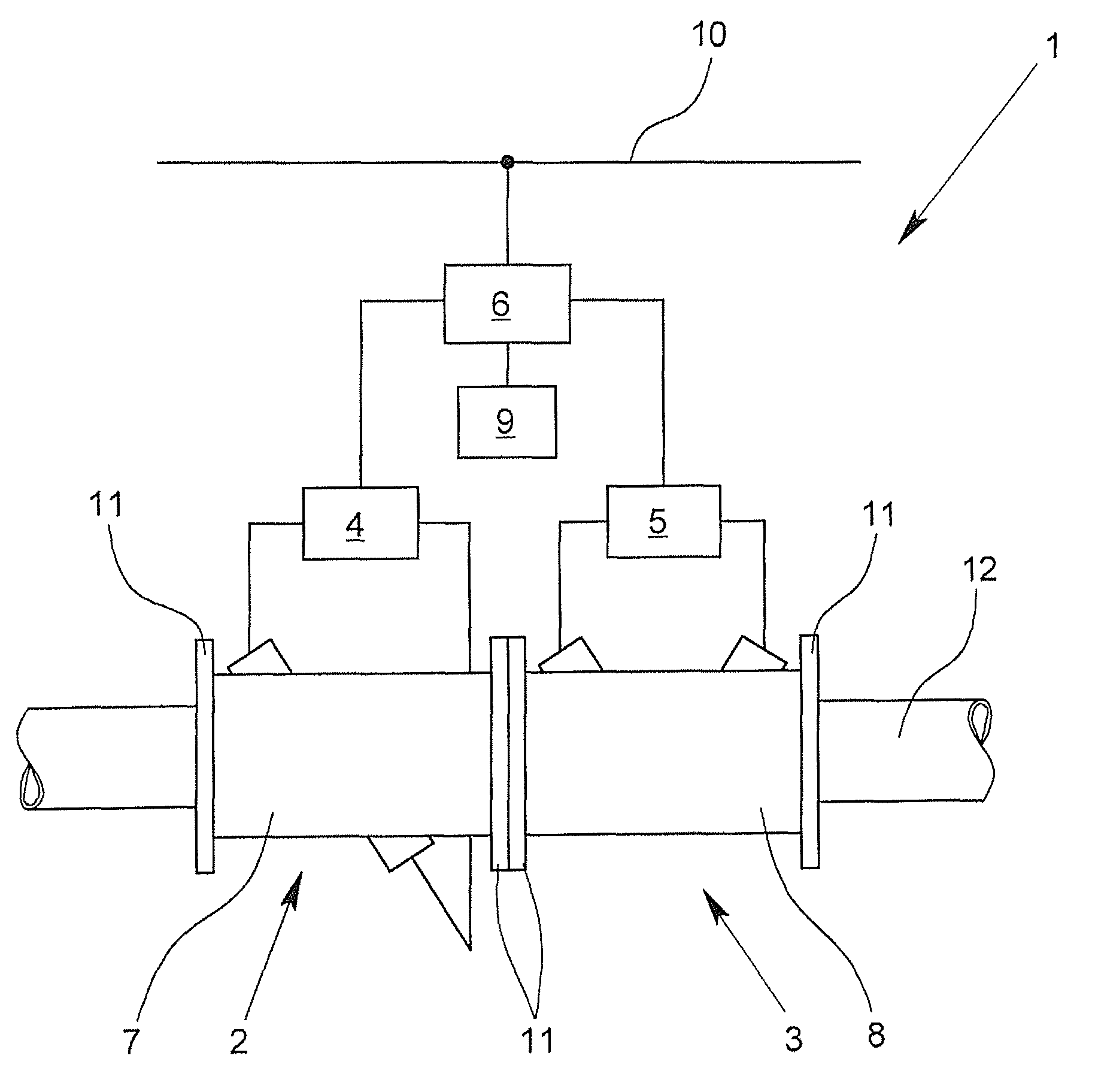
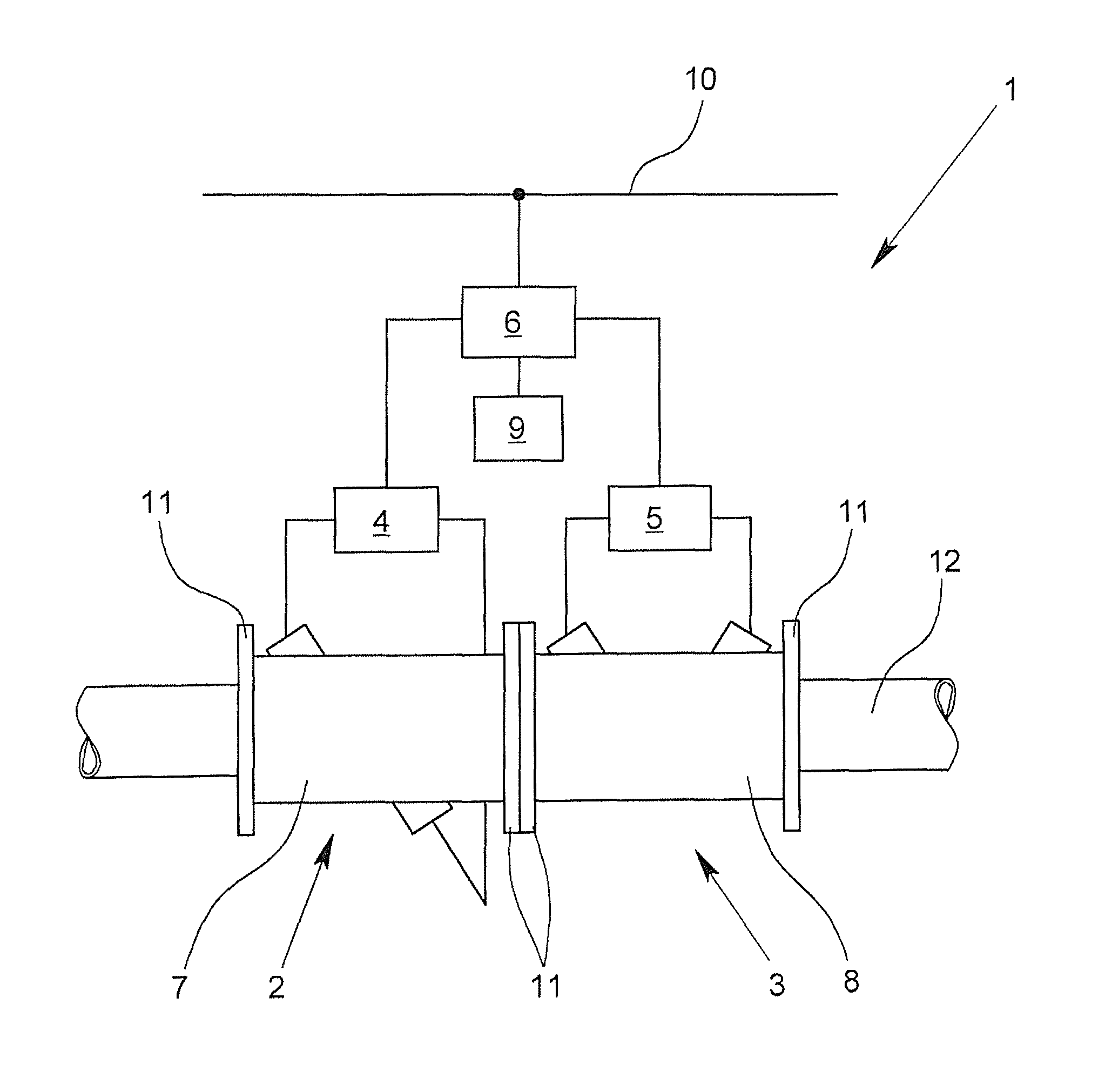
[0028]The FIGURE shows purely schematically a system 1 for measuring the flow rate of a measurement medium, which is especially a gas or gas mixture, but could be a liquid or a particulate solid. For this purpose, there are two flow meters 2, 3 which are made as ultrasonic flow meters. The first flow meter 2 and the second flow meter 3 differ in the arrangement of the ultrasonic transducers, and thus, by the path taken by the ultrasonic signals for the measurement. On the one hand, with reflection on the wall of the respective measurement tube, and on the other hand, without reflection on the wall of the respective measurement tube. The measurement signals are evaluated in the evaluation units 4, 5 which generate not only a value for the flow rate, but also secondary data about the measurement or about the flow rate, and which transfer these secondary data to the monitoring device 6. These secondary data are, for example, uncertainties of the measurement value of the flow rate, nois...


PUM


Abstract

A system for measuring flow rate with at least a first and a second flow meter provides a flow-rate measurement system which easily allows self-monitoring. This result is achieved by the system in that the first flow meter and the second flow meter differ from one another and / or have different orientations for the flow rate measurement, and each have an evaluation unit which produces data from the flow rate measurement. Furthermore, there is a monitoring device which is connected to the evaluation units such that the monitoring device acquires data produced by the evaluation units, and which is made such that it produces at least one comparison result from a comparison of the data produced by the evaluation units and signals at least the occurrence of a fault state which is associated with at least one comparison result.

Description

BACKGROUND OF THE INVENTION[0001]1. Field of the Invention[0002]The invention relates to a system for measuring flow rate with at least one first flow meter and one second flow meter.[0003]2. Description of Related Art[0004]Aside from the fact that high measurement accuracy in any flow rate measurement is always desirable from a technical standpoint, for high-value liquid or gaseous products, such as, for example, petroleum and natural gas, there is considerable interest in the fact that, from the standpoint of the supplier, the amount and only the amount which is to be delivered is delivered, and from the standpoint of the consumer, that the required amount and at least the required amount is obtained. Measurement tolerances are always a burden to one of the parties involved, usually to the burden of the supplier.[0005]Known measurement methods for determining the flow rate use, for example, the transit time of ultrasonic waves, the time being transmitted either directly between th...

Claims


Application Information

Patent Timeline
Patent Type & Authority Patents(United States)
IPC IPC(8): G01F1/00G01F1/712G01F1/66G01F7/00G01F25/00
CPCG01F7/00G01F25/0007G01F25/003G01F1/667G01F25/13G01F25/10
Inventor KURTH, MARTINDRENTHEN, JANVERNEULEN, MARCEL
Owner KRONE GMBH
Why Eureka
Try Eureka