Rail recovery system for aircraft

a rail recovery and aircraft technology, applied in the direction of aircrafts, transportation and packaging, and anchors, can solve the problems of not being able to facilitate the use of runways, vtol platforms, ineffective, and often lack of endurance, and achieve the effect of reducing the footprin

Inactive Publication Date: 2015-04-21
AURORA FLIGHT SCI CORP
View PDF43 Cites 63 Cited by
  • Summary
  • Abstract
  • Description
  • Claims
  • Application Information

AI Technical Summary

Problems solved by technology

Unfortunately, because of land limitations or other space constrictions, not all situations facilitate runway usage.
Moreover, runway independent UASs enable organic UAV deployment from locations where traditional runways may not be feasible, including, for example, ships, trucks, forward operating bases, clandestine locales, payload emplacements, and transitory emplacements.
VTOL platforms, while effective, often lack endurance because they need large, inefficient power plants to take off and land.
Despite the advances in VTOL technology, fixed-wing UASs typically offer greater performance than VTOLs, but they are not inherently runway independent.
Recovery, on the other hand, has traditionally been more difficult because of the challenges posed by, for example, precision engagement, energy absorption, and post-capture handling.
Furthermore, fixed-wing recovery systems such as nets and vertical cables are typically only practical on small UAVs and UASs.
Each of these legacy recovery approaches, however, has limitations for UASs having UAVs that weigh more than a few hundred pounds.
These limitations may be attributed to, for example, unpredictable dynamic loads, poor precision, airframe-recovery system physical interface challenges, or excessive shock.
Though partially effective, using a net to catch a UAV in flight often resulted in damage to the airframe and a high loss rate.
Similarly, positioning a net astern of the ship would increase the likelihood of loss if the aircraft missed the net and hit the ship instead.
Though effective for miniature robotic aircraft, its method of hooking a wingtip and securing the air vehicle at a single point after capture, make the SkyHook™ ineffective for larger UAVs.

Method used


Image

  • Rail recovery system for aircraft
  • Rail recovery system for aircraft
  • Rail recovery system for aircraft

Examples


Embodiment Construction

[0046]Embodiments of the present invention are described hereinbelow with reference to the accompanying drawings. In the following description, well-known functions or constructions are not described in detail because they would obscure the invention in unnecessary detail.

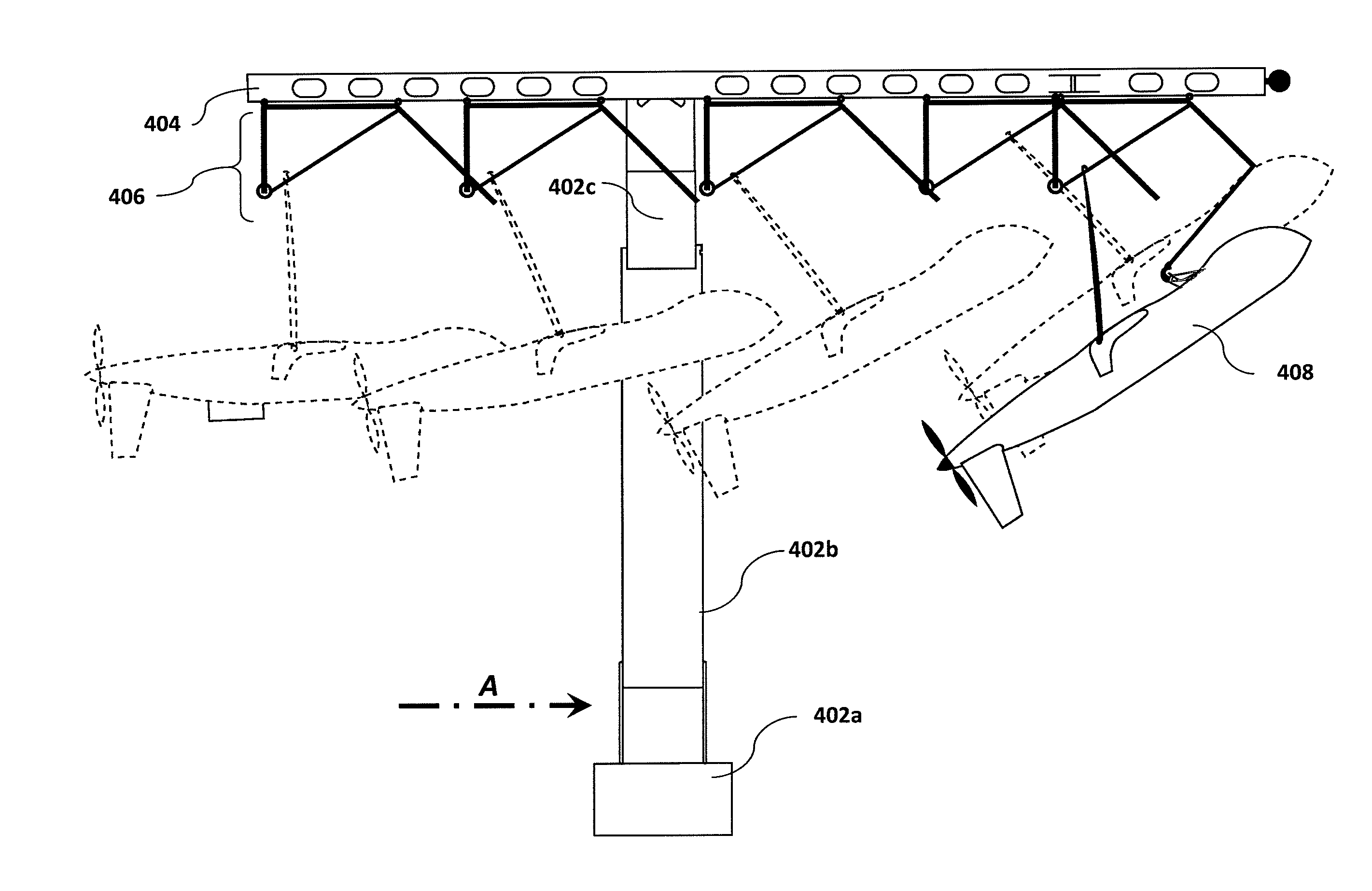
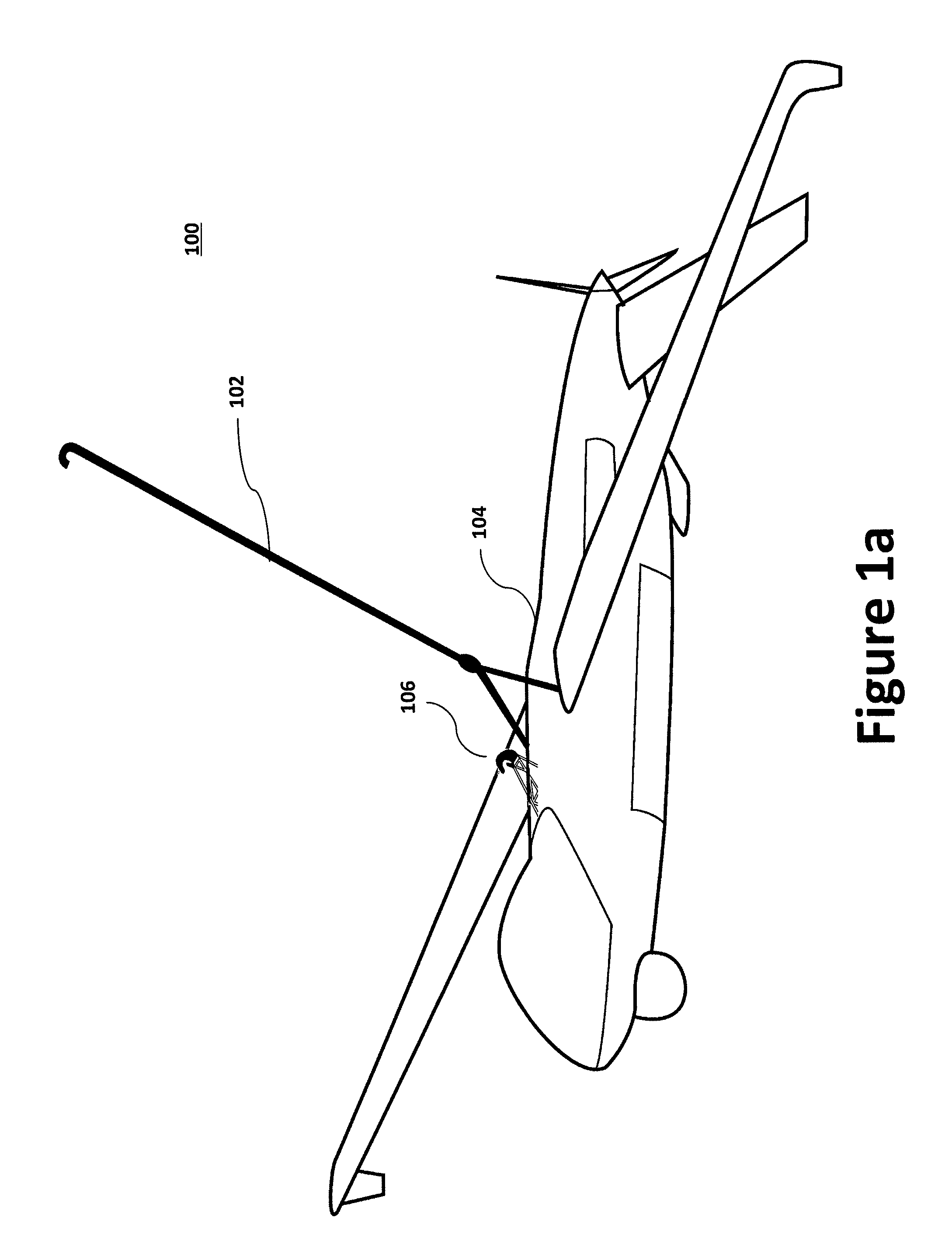
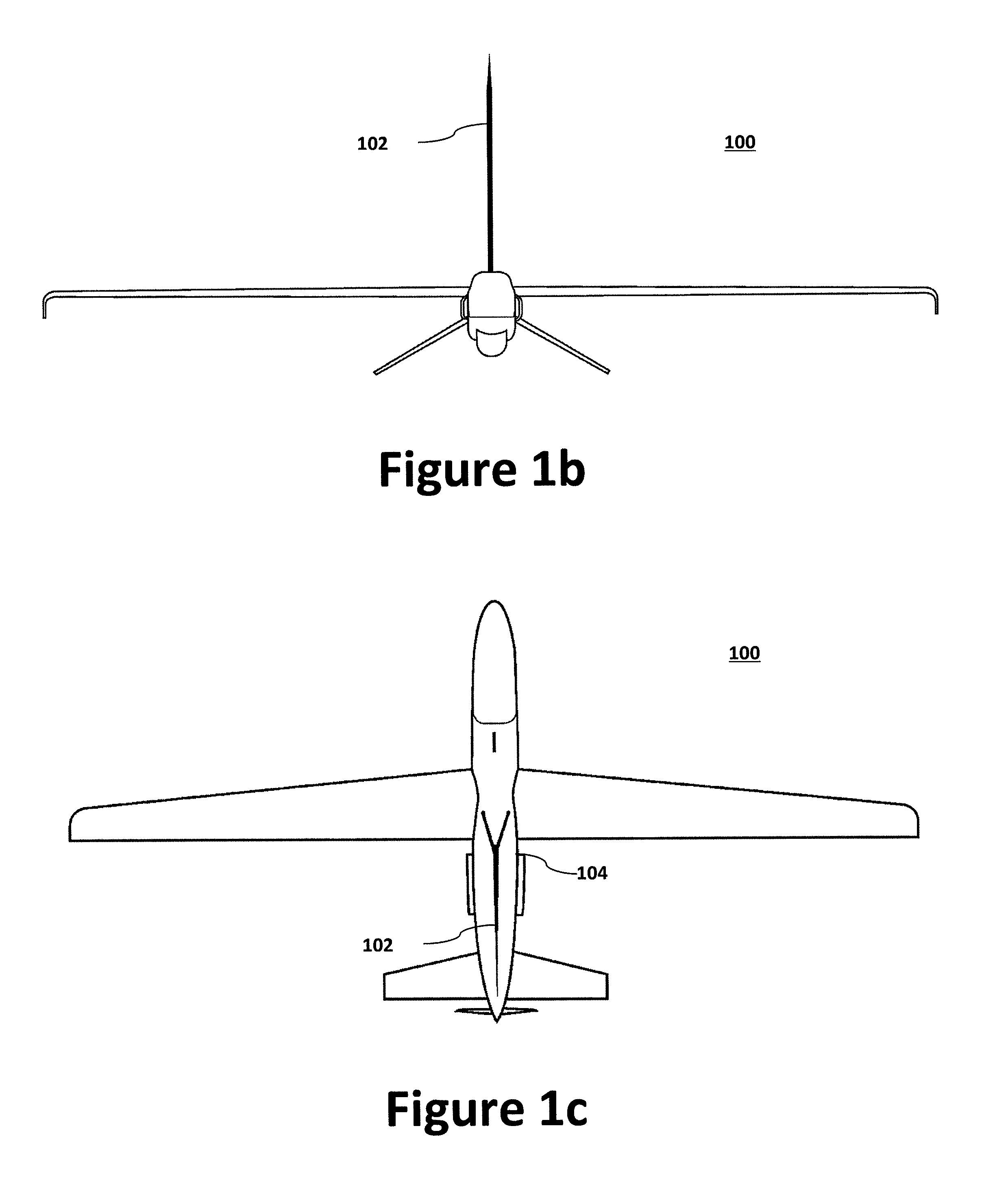
[0047]Because of continuing advancements in UAS and UAV technology, the use of UAVs has continued to grow. For example, the Aurora Perseus-N design offers excellent mission performance and, when in the stowed position, occupies only 64×470 inches of hangar space—roughly half the footprint of an MH-60 helicopter. Although UAVs such as the Perseus-N offer excellent mission performance in the air, when runways are unavailable, suitable mechanisms should be provided to facilitate launch and recovery. Therefore, as discussed below, UASs such as the Perseus-N may be configured to utilize a top-hook assembly with a side-arm recovery system to facilitate effective launch and recovery.

[0048]As discussed in greater detail be...


PUM


Abstract

The present invention's side-arm recovery system enables large Unmanned Aircraft Systems (UASs) to operate from small vessels or from ground sites with a minimal footprint. The side-arm recovery system allows arresting an UAS independent of a runway. On the ground or on a ship, the system makes use of a specialized crane system that includes capture and energy absorption devices. A fuselage-mounted top hook snags a horizontal cable and the arresting forces act in the plane of symmetry through the central structure of the UAS. After the capture energy is absorbed, the recovery system safely lowers the aerial vehicle to a ground handling cart. The same system can be combined into a launcher and retriever system which further reduces the footprint by eliminating the need for a separate launcher.

Description

CROSS-REFERENCE TO RELATED APPLICATIONS[0001]This application claims priority to U.S. Provisional Patent Application No. 61 / 541,429, filed on Sep. 30, 2011, entitled “Rail Recovery System For Aircraft,” by Jay Gundlach et al., which is hereby incorporated by reference.TECHNICAL FIELD[0002]The present invention relates to systems and methods for use with Unmanned Aerial Vehicles (“UAVs”) and Unmanned Aerial Systems (“UASs”). More specifically, the present invention relates to systems and methods for enabling the operation of UAVs and UASs from small vessels or from ground sites with minimal footprints.BACKGROUND INFORMATION[0003]As is well known in the art, fixed-wing aircraft typically require a runway to take off and land. And a runway requires a large surface area, be it man-made (e.g., asphalt, concrete, or a mixture of both) or natural (e.g., grass, dirt, gravel, ice, or salt). Unfortunately, because of land limitations or other space constrictions, not all situations facilitate...

Claims


Application Information

Patent Timeline
Patent Type & Authority Patents(United States)
IPC IPC(8): B64F1/02B64C25/68B64C39/02
CPCB64C25/68B64F1/02B64C39/024B64C2201/182B64F1/029B64F1/0299B64U70/30B64U10/25
Inventor GUNDLACH, JOHNBOURVEN, JEAN-MARIEGIANNINI, FRANCESCOPETULLO, STEVENCLANCY, THOMAS
Owner AURORA FLIGHT SCI CORP
Why Eureka
Try Eureka